
User's Manual

15
15
english
Power TP
Power TP
BIS L-405
Installation
Metal frame
Installation
BIS L-405
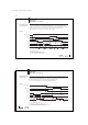
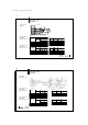
When installing two BIS L-405 on a metal base, there is normally no mutual interference. If
a metal frame is located in an unfavorable location, problems may result when reading out
the data carriers. In this case the read distance will be reduced to 80 % of the maximum
value.
Testing is recommended in critical applications!
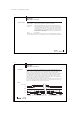
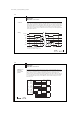
Once a data carrier has been processed in front of a read head, the next data carrier must
wait 400 ms before being introduced into the active field. This can be implemented by
means of a stopper. If a stopper is not used, there is a rule of thumb which takes into
account the conveyor speed. Distance between the data carriers in m = (0.4 x conveyor
speed in m/s) + 0.25 m.
Example: Conveyor speed = 1 m/s
Distance = (0.4 x 1 m/s) + 0.25 m = 0.65 m
This is an approximation for the worst case.
When using small data carriers and/or small read heads, the distance is reduced considerably!
BIS L-405-03_-00_-05-MU_834487_E_0709.p65
16
english16
BIS L-405
Installation
Installation
BIS L-405,
permissible
distances
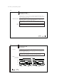
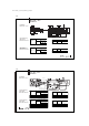
Distance from data carrier to data carrier
BIS L-200-03/L BIS L-201-03/L BIS L-202-03/L
BIS L-405-033 > 25 cm > 30 cm > 40 cm
BIS L-100-05/L BIS L-101-05/L BIS L-102-05/L
BIS L-405-037 > 25 cm > 30 cm > 40 cm
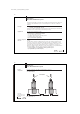
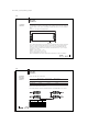
Distance from read head to read head
The following distances must be maintained between the individual BIS L-405 systems:
X
Y
Distance X Distance Y
BIS L-405-...-001-... 1 m 1 m
BIS L-405-...-002-... 0.5 m 0.3 m
BIS L-405-...-003-... 0.5 m 0.3 m
BIS L-405-...-004-... 0.5 m 0.3 m