
User Manual


CHAPTER 5: RFID TAGS
COBALT HF RFID CONTROLLERS OPERATOR’S MANUAL
P/N: 17-1320 REV 01 (03-06) PAGE 57 OF 116
5.5 TAG M EMORY
Tag memory addressing begins at address 00 (0x0000), with the highest addressable
memory location equal to one less than the total number of bytes in the tag. Each
address is equal to one byte (8-bits), where the byte is the smallest addressable unit of
data. So for example, writing 8-bytes to a tag beginning at address 00 will actually fill
addresses 00 through 07 with 64-bits of data in all.
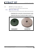
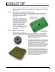
Depending on the manufacturer, RFID labels, molded tags and embedded PCBs can
have differing memory storage capacities
and organization. Tag memory is grouped into
blocks of bytes that can vary in structure from manufacturer to manufacturer. Even when
compliant to ISO standards, byte memory addressing can differ from one manufacturer to
another. For example, tag memory can be organized in blocks of 4 or 8 bytes, depending
on the RFID IC. Additionally, all bytes may not be available for data storage as some
bytes may be used for security and access conditions. For more information regarding a
specific RFID tag’s memory allocation, please refer to IC manufacturer’s published
datasheet or Website.
Escort Memory Systems has taken great care to simplify tag memory addressing. The
mapping from logical address to physical address is handled by the Cobalt Controller’s
operating system. Users only need to indicate the starting address location on the tag
and the number of bytes to be read or written.
Is it a Bit or a Byte?
Customers need to understand that there are some RFID tag manufacturers that
measure and specify their tag memory size by the total number of bits, as this method
generates a much larger (8X) overall number. Escort Memory Systems, on the other
hand, prefers to specify total tag memory size in terms of bytes (rather than in bits), as
this method more closely reflects how data is stored and retrieved from a tag and is
typically what users really want to know.
5.5.1 Mapping Tag Memory
Creating an RFID Tag Memory Map
Creating a Tag Memory Map is much like creating a spreadsheet that outlines the actual
data you plan to capture as well as the specific tag memory locations in which you wish
to store said data. Tag Memory maps should be carefully planned, simple and
straightforward. It is advisable to allow additional memory space than is initially required
as inevitably a need will arise to store more data.
In the example below, 90-bytes of a 112-byte tag have been allocated to areas of the
Memory Map (leaving roughly 20% free for future uses). Because a short paragraph of
alphanumeric characters could quickly use all 90 bytes, creating an efficient mapping
scheme which utilizes all 720-bits (out of the 90-bytes allocated) will provide a better use
of tag space.