
User Manual


CHAPTER 5: RFID TAGS
COBALT HF RFID CONTROLLERS OPERATOR’S MANUAL
P/N: 17-1320 REV 01 (03-06) PAGE 58 OF 116
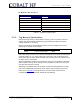
TAG M EMORY M AP E XAMPLE
TAG ADDRESS USAGE
00 – 15
Serial #
16 - 47
Model #
48 - 63
Production Date
64 - 71
Lot #
72 - 89
Factory ID
90 - 111
Reserved for Future Use
Table 5-1: Tag Memory Map Example
5.5.2 Tag Memory Optimization
Data stored in tag memory is always written in binary (1’s and 0’s). Binary values are
notated using the hexadecimal numbering system (otherwise it might be confusing
viewing a page full of 1’s and 0’s).
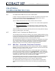
Below is an example of how hexadecimal notation is used to simplify the process of
expressing the decimal number 52,882.
Decimal Binary Hexadecimal
52,882 1100 1110 1001 0010 CE92
Rather than using five bytes to store the five individual ASCII characters representing the
numerical values 5, 2, 8, 8, and 2 (ASCII bytes: 0x35, 0x32, 0x38, 0x38 and 0x32), by
simply writing two Hex bytes (0xCE and 0x92), 60% less tag memory is required to store
the same amount of information.
When an alphabetical character is to be written to a tag, the Hex equivalent of the ASCII
value is written to the tag. So for example, to write a capital “D” (ASCII value 0x44), the
Hex value 0x44 is written to the tag.
Additionally, if a database with look up values is used in the RFID application, the logic
level of the individual bits within the tag can be used to further maximize tag memory.
(Note: refer to
Appendix D
in this document for a chart of ASCII characters, their
corresponding Hex values and their decimal value equivalents).