
User Manual
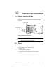


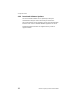
Table Of Contents
- LRP75 Long Range Passive Reader/Writer
- Table of Contents
- Getting Started
- Mechanical Specifications
- Power and Electrical Interface
- Configuration Menu
- Standard RFID Interface
- 5.1 Introduction
- 5.2 Command Timeout Values
- 5.3 Address Blocks
- 5.4 ABx Error Codes
- 5.5 Command Descriptions
- 5.6 ABx Standard Commands
- 5.6.1 Command 4 (04 Hex): Tag Fill
- 5.6.2 Command 5 (05 Hex): Block Read
- 5.6.3 Command 6 (06 Hex): Block Write
- 5.6.4 Command 7 (07H): Read Tag Serial Number
- 5.6.5 Command 8 (08 Hex): Tag Search
- 5.6.6 Command D (0D Hex): Start/Stop Continuous Block Read
- 5.6.7 Command E (0EH) Read SN and Data
- 5.6.8 Command F (0FH) Start/Stop Continuous Read SN and Data
- 5.7 ABx Fast Commands
- 5.7.1 ABx Command Packet Structure
- 5.7.2 Command 4 (04 Hex): Tag Fill
- 5.7.3 Command 5 (05 Hex): Block Read
- 5.7.4 Command 6 (06 Hex): Block Write
- 5.7.5 Command 7 (07H): Read Tag Serial Number
- 5.7.6 Command 8 (08 Hex): Tag Search
- 5.7.7 Command D (0D Hex): Start/Stop Continuous Block Read
- 5.7.8 Command E (0EH) Read SN and Data
- 5.7.9 Command F (0FH) Start/Stop Continuous Read SN and Data
- Technical Specifications
- LRP75 Beta Connections
- Models and Accessories
- ASCII Chart

LRP75 Long Range Passive Reader/Writer 7
3
Power and Electrical Interface
3.1 Internal Junction Blocks
The LRP75 is connected to external power and communications
cabling through an internal terminal strip. The power and serial
communication junction block (J1) has 10 terminals and accepts AWG
22-14 wires.
Figure 3-1. Internal junction block
NOTE:Earlier models of the LRP75 have different power and serial
communications connections. For more information, see
Appendix B,
LRP75 Beta Connections
.
3.2 Power
3.2.1 Requirement
The LRP75 power supply requirements are:
• 24 Vdc +/- 10%
• 5 Watts maximum consumption
The maximum current consumption at 24 Vdc is 200 mA.
J1 Terminal Block
Ground Screw