
User Manual
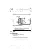


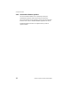
Table Of Contents
- LRP75 Long Range Passive Reader/Writer
- Table of Contents
- Getting Started
- Mechanical Specifications
- Power and Electrical Interface
- Configuration Menu
- Standard RFID Interface
- 5.1 Introduction
- 5.2 Command Timeout Values
- 5.3 Address Blocks
- 5.4 ABx Error Codes
- 5.5 Command Descriptions
- 5.6 ABx Standard Commands
- 5.6.1 Command 4 (04 Hex): Tag Fill
- 5.6.2 Command 5 (05 Hex): Block Read
- 5.6.3 Command 6 (06 Hex): Block Write
- 5.6.4 Command 7 (07H): Read Tag Serial Number
- 5.6.5 Command 8 (08 Hex): Tag Search
- 5.6.6 Command D (0D Hex): Start/Stop Continuous Block Read
- 5.6.7 Command E (0EH) Read SN and Data
- 5.6.8 Command F (0FH) Start/Stop Continuous Read SN and Data
- 5.7 ABx Fast Commands
- 5.7.1 ABx Command Packet Structure
- 5.7.2 Command 4 (04 Hex): Tag Fill
- 5.7.3 Command 5 (05 Hex): Block Read
- 5.7.4 Command 6 (06 Hex): Block Write
- 5.7.5 Command 7 (07H): Read Tag Serial Number
- 5.7.6 Command 8 (08 Hex): Tag Search
- 5.7.7 Command D (0D Hex): Start/Stop Continuous Block Read
- 5.7.8 Command E (0EH) Read SN and Data
- 5.7.9 Command F (0FH) Start/Stop Continuous Read SN and Data
- Technical Specifications
- LRP75 Beta Connections
- Models and Accessories
- ASCII Chart

Power and Electrical Interface
10 LRP75 Long Range Passive Reader/Writer
3.5.1 RS232 and Power Cable
Figure 3-2 shows how to construct a demonstration cable with power
and RS232 serial communications to a PC host with a DE9 serial port
connector.
Figure 3-2. LRP75 to PC host demo
3.5.2 Wiring
Use shielded cable only. Connect shield drain of the power and data
cabling to either ground on the J1 connector (terminal 2 or 4).
• Recommended cable for RS422 is Belden 3107A, 3108A or
compatible.
• Recommended cable for RS232 is Belden 9941 or compatible.
To fully comply with FCC and CE Regulations, wind the power and
data cabling around a type 43 ferrite toroid such as Fairrite™ part
number 2643803802 or Amidon™ part number FT-240-43. Install the
toroid as close as possible to the LRP75’s gland nut. You must
connect the internal ground screw, shown in Figure 3-1 on page 7, to
the nearest earth ground outside the unit.
To make the ground connection, first terminate a length of 1/8-inch
copper braid with a ring terminal such as Panduit™ part number P18-
45. Fasten the ring terminal to the ground screw. For a tight seal,
chase the braid through the gland nut against the data and power
cabling.