
User Manual
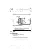
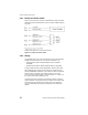
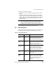


Table Of Contents
- LRP75 Long Range Passive Reader/Writer
- Table of Contents
- Getting Started
- Mechanical Specifications
- Power and Electrical Interface
- Configuration Menu
- Standard RFID Interface
- 5.1 Introduction
- 5.2 Command Timeout Values
- 5.3 Address Blocks
- 5.4 ABx Error Codes
- 5.5 Command Descriptions
- 5.6 ABx Standard Commands
- 5.6.1 Command 4 (04 Hex): Tag Fill
- 5.6.2 Command 5 (05 Hex): Block Read
- 5.6.3 Command 6 (06 Hex): Block Write
- 5.6.4 Command 7 (07H): Read Tag Serial Number
- 5.6.5 Command 8 (08 Hex): Tag Search
- 5.6.6 Command D (0D Hex): Start/Stop Continuous Block Read
- 5.6.7 Command E (0EH) Read SN and Data
- 5.6.8 Command F (0FH) Start/Stop Continuous Read SN and Data
- 5.7 ABx Fast Commands
- 5.7.1 ABx Command Packet Structure
- 5.7.2 Command 4 (04 Hex): Tag Fill
- 5.7.3 Command 5 (05 Hex): Block Read
- 5.7.4 Command 6 (06 Hex): Block Write
- 5.7.5 Command 7 (07H): Read Tag Serial Number
- 5.7.6 Command 8 (08 Hex): Tag Search
- 5.7.7 Command D (0D Hex): Start/Stop Continuous Block Read
- 5.7.8 Command E (0EH) Read SN and Data
- 5.7.9 Command F (0FH) Start/Stop Continuous Read SN and Data
- Technical Specifications
- LRP75 Beta Connections
- Models and Accessories
- ASCII Chart

Power and Electrical Interface
LRP75 Long Range Passive Reader/Writer 11
To connect your cable to the LRP75:
1. Remove the cover of the antenna by loosening the four captive
screws.
2. Loosen the cord grip, feed the cable through the cord grip and
attach the wires to the terminal screws. Tighten the cord grip to
seal the cable. Use a cable of sufficient diameter to properly seal
with the cord grip. The recommended minimum O.D. is .125
inches (3.2 mm).
NOTE:Due to the small size of the LRP75 enclosure and gland nut,
you may have difficulty sealing wires passing through the
gland nut. Olflex
®
cable part number 911285 is readily
available and will satisfy the requirements of most applications.
3. Re-assemble the enclosure and secure the screws.
3.6 LED Indicator
The LRP75 has one bi-color LED indicating power on and activity on
the serial port. Table 3-3 shows the LED activity and meaning.
Table 3-3: LRP75 LED Indicator
LED Action LRP75 state Description
Slow RED
Blink
Power-up or
reset
The LED will flash RED slowly for about
seven seconds following power-up
during which time the user may send a
<Ctrl> D to enter configuration mode.
Fast RED
Blink
Configuration
mode
If the LRP75 receives a <Ctrl> D during
the initial seven second period, the LED
will flash at a faster rate until
configuration mode has been exited.
Steady
GREEN
Idle The unit is ready for an ABx command.
A steady GREEN LED indicates that the
seven second period has elapsed
without entering configuration mode, or
configuration has been completed.
GREEN
Blink
LRP75
upgrade
While downloading a new, or custom,
program to the LRP75, the LED will
blink GREEN.
Short RED/
GREEN
Blink
Executing
Command
While the reader/writer is occupied with
a command, the LED will be flashing
GREEN to RED. A RED to GREEN
flash indicates a tag is being searched
for, and the command is being
executed.