
User Manual
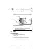
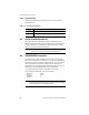
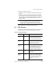


Table Of Contents
- LRP75 Long Range Passive Reader/Writer
- Table of Contents
- Getting Started
- Mechanical Specifications
- Power and Electrical Interface
- Configuration Menu
- Standard RFID Interface
- 5.1 Introduction
- 5.2 Command Timeout Values
- 5.3 Address Blocks
- 5.4 ABx Error Codes
- 5.5 Command Descriptions
- 5.6 ABx Standard Commands
- 5.6.1 Command 4 (04 Hex): Tag Fill
- 5.6.2 Command 5 (05 Hex): Block Read
- 5.6.3 Command 6 (06 Hex): Block Write
- 5.6.4 Command 7 (07H): Read Tag Serial Number
- 5.6.5 Command 8 (08 Hex): Tag Search
- 5.6.6 Command D (0D Hex): Start/Stop Continuous Block Read
- 5.6.7 Command E (0EH) Read SN and Data
- 5.6.8 Command F (0FH) Start/Stop Continuous Read SN and Data
- 5.7 ABx Fast Commands
- 5.7.1 ABx Command Packet Structure
- 5.7.2 Command 4 (04 Hex): Tag Fill
- 5.7.3 Command 5 (05 Hex): Block Read
- 5.7.4 Command 6 (06 Hex): Block Write
- 5.7.5 Command 7 (07H): Read Tag Serial Number
- 5.7.6 Command 8 (08 Hex): Tag Search
- 5.7.7 Command D (0D Hex): Start/Stop Continuous Block Read
- 5.7.8 Command E (0EH) Read SN and Data
- 5.7.9 Command F (0FH) Start/Stop Continuous Read SN and Data
- Technical Specifications
- LRP75 Beta Connections
- Models and Accessories
- ASCII Chart

Power and Electrical Interface
12 LRP75 Long Range Passive Reader/Writer
RED and
GREEN
Executing
Continuous
Block Read
The LED will be both RED and GREEN
(orange) indicates the LRP75 is in
continuous mode. There is short RED
flash when data sent to the host.
1
1. When Software Handshaking is enabled, and the host has sent
the LRP75 an XOFF, the RED LED will be on while the LRP75
transmit buffer fills. The LED will remain RED until an XON is
received and the LRP buffer is emptied.
Table 3-3: LRP75 LED Indicator
LED Action LRP75 state Description