
User Manual
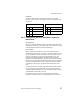
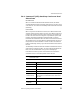
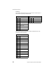

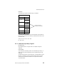
Table Of Contents
- LRP75 Long Range Passive Reader/Writer
- Table of Contents
- Getting Started
- Mechanical Specifications
- Power and Electrical Interface
- Configuration Menu
- Standard RFID Interface
- 5.1 Introduction
- 5.2 Command Timeout Values
- 5.3 Address Blocks
- 5.4 ABx Error Codes
- 5.5 Command Descriptions
- 5.6 ABx Standard Commands
- 5.6.1 Command 4 (04 Hex): Tag Fill
- 5.6.2 Command 5 (05 Hex): Block Read
- 5.6.3 Command 6 (06 Hex): Block Write
- 5.6.4 Command 7 (07H): Read Tag Serial Number
- 5.6.5 Command 8 (08 Hex): Tag Search
- 5.6.6 Command D (0D Hex): Start/Stop Continuous Block Read
- 5.6.7 Command E (0EH) Read SN and Data
- 5.6.8 Command F (0FH) Start/Stop Continuous Read SN and Data
- 5.7 ABx Fast Commands
- 5.7.1 ABx Command Packet Structure
- 5.7.2 Command 4 (04 Hex): Tag Fill
- 5.7.3 Command 5 (05 Hex): Block Read
- 5.7.4 Command 6 (06 Hex): Block Write
- 5.7.5 Command 7 (07H): Read Tag Serial Number
- 5.7.6 Command 8 (08 Hex): Tag Search
- 5.7.7 Command D (0D Hex): Start/Stop Continuous Block Read
- 5.7.8 Command E (0EH) Read SN and Data
- 5.7.9 Command F (0FH) Start/Stop Continuous Read SN and Data
- Technical Specifications
- LRP75 Beta Connections
- Models and Accessories
- ASCII Chart

Standard RFID Interface
34 LRP75 Long Range Passive Reader/Writer
If the LRP75 encounters a fault, it will respond with the following:
• The Header and Terminator are always STX-STX and ETX
respectively.
• All other bytes are interpreted as binary data (0 - 255 dec).
• Fields with two bytes are sent most significant byte (MSB) first.
The sequence for each command is given with the response format in
the following section.
Command/Response Size
The ABx Fast requires that the length of the packet be included in the
command. All parameters and data between the Command/Response
Size and the Checksum or Terminator bytes must be accounted for in
the command/response size word. This includes all command codes
and parameters such as field definitions for Block Read/Writes. The
command/response size will be the same with, or without, a
checksum.
Checksum
The optional checksum must be enabled from the operating mode
menu to be available. The checksum is calculated by adding all the
byte values in the packet (less the values in the header, checksum if
present, and terminator), discarding byte overflow and subtracting the
byte sum from FFH. Thus, when the packet length through the
checksum are added as byte values, the sum will be FFH.
Field
Number
of Bytes
Description
Header 2 <STX><STX> (02H, 02H)
Response
Size
2 Packet length in bytes excluding the header,
command size, checksum and terminator
bytes.
Error Flag 1 FFH
Error Code 1 Hex error code
Checksum 1 Optional Checksum
Terminator 1 <ETX> (03H)