
User Manual
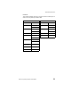
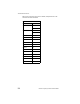


Table Of Contents
- LRP75 Long Range Passive Reader/Writer
- Table of Contents
- Getting Started
- Mechanical Specifications
- Power and Electrical Interface
- Configuration Menu
- Standard RFID Interface
- 5.1 Introduction
- 5.2 Command Timeout Values
- 5.3 Address Blocks
- 5.4 ABx Error Codes
- 5.5 Command Descriptions
- 5.6 ABx Standard Commands
- 5.6.1 Command 4 (04 Hex): Tag Fill
- 5.6.2 Command 5 (05 Hex): Block Read
- 5.6.3 Command 6 (06 Hex): Block Write
- 5.6.4 Command 7 (07H): Read Tag Serial Number
- 5.6.5 Command 8 (08 Hex): Tag Search
- 5.6.6 Command D (0D Hex): Start/Stop Continuous Block Read
- 5.6.7 Command E (0EH) Read SN and Data
- 5.6.8 Command F (0FH) Start/Stop Continuous Read SN and Data
- 5.7 ABx Fast Commands
- 5.7.1 ABx Command Packet Structure
- 5.7.2 Command 4 (04 Hex): Tag Fill
- 5.7.3 Command 5 (05 Hex): Block Read
- 5.7.4 Command 6 (06 Hex): Block Write
- 5.7.5 Command 7 (07H): Read Tag Serial Number
- 5.7.6 Command 8 (08 Hex): Tag Search
- 5.7.7 Command D (0D Hex): Start/Stop Continuous Block Read
- 5.7.8 Command E (0EH) Read SN and Data
- 5.7.9 Command F (0FH) Start/Stop Continuous Read SN and Data
- Technical Specifications
- LRP75 Beta Connections
- Models and Accessories
- ASCII Chart

LRP75 Long Range Passive Reader/Writer 57
Appendix B
LRP75 Beta Connections
Early models of the LRP75 have two terminal blocks for power and
serial communication. If you are wiring a LRP75 Beta unit, use the
pinouts given in this appendix.
B.1 Internal Junction Blocks
The LRP75 is connected to external power and communications
cabling through two internal terminal blocks. The power and serial
communication junction blocks accept AWG 22-14 wires.
Figure B-1. Internal junction block
B.2 Power Connections
Connection to power is through the internal J2 terminal block.
Table 5-3: J2 Power Connection
Terminal Description
1+24 Vdc
2 Power Ground