
User Manual


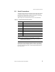


Table Of Contents
- LRP76 Long Range Passive Reader/Writer
- Table of Contents
- Getting Started
- Mechanical Specifications
- Power and Electrical Interface
- Configuration Menu
- Standard RFID Interface
- 5.1 Introduction
- 5.2 Command Timeout Values
- 5.3 Address Blocks
- 5.4 ABx Error Codes
- 5.5 Command Descriptions
- 5.6 ABx Standard Commands
- 5.6.1 Command 4 (04 Hex): Tag Fill
- 5.6.2 Command 5 (05 Hex): Block Read
- 5.6.3 Command 6 (06 Hex): Block Write
- 5.6.4 Command 7 (07H): Read Tag Serial Number
- 5.6.5 Command 8 (08 Hex): Tag Search
- 5.6.6 Command D (0D Hex): Start/Stop Continuous Block Read
- 5.6.7 Command E (0EH) Read SN and Data
- 5.6.8 Command F (0FH) Start/Stop Continuous Read SN and Data
- 5.7 ABx Fast Commands
- 5.7.1 ABx Command Packet Structure
- 5.7.2 Command 4 (04 Hex): Tag Fill
- 5.7.3 Command 5 (05 Hex): Block Read
- 5.7.4 Command 6 (06 Hex): Block Write
- 5.7.5 Command 7 (07H): Read Tag Serial Number
- 5.7.6 Command 8 (08 Hex): Tag Search
- 5.7.7 Command D (0D Hex): Start/Stop Continuous Block Read
- 5.7.8 Command E (0EH) Read SN and Data
- 5.7.9 Command F (0FH) Start/Stop Continuous Read SN and Data
- Technical Specifications
- Models and Accessories
- ASCII Chart

LRP76 Long Range Passive Reader/Writer 7
3
Power and Electrical Interface
3.1 Internal Junction Blocks
The LRP76 is connected to external power and communications
cabling through an internal terminal strips. The terminal accepts AWG
22-14 wires.
Figure 3-1. Internal junction block
3.2 Power
3.2.1 Requirement
The LRP76 power supply requirements are:
• 24 Vdc +/- 10%
• 5 Watts maximum consumption
The maximum current consumption at 24 Vdc is 200 mA.
J1 Terminal Block
Ground Screw