
User Manual


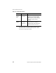

Table Of Contents
- LRP76 Long Range Passive Reader/Writer
- Table of Contents
- Getting Started
- Mechanical Specifications
- Power and Electrical Interface
- Configuration Menu
- Standard RFID Interface
- 5.1 Introduction
- 5.2 Command Timeout Values
- 5.3 Address Blocks
- 5.4 ABx Error Codes
- 5.5 Command Descriptions
- 5.6 ABx Standard Commands
- 5.6.1 Command 4 (04 Hex): Tag Fill
- 5.6.2 Command 5 (05 Hex): Block Read
- 5.6.3 Command 6 (06 Hex): Block Write
- 5.6.4 Command 7 (07H): Read Tag Serial Number
- 5.6.5 Command 8 (08 Hex): Tag Search
- 5.6.6 Command D (0D Hex): Start/Stop Continuous Block Read
- 5.6.7 Command E (0EH) Read SN and Data
- 5.6.8 Command F (0FH) Start/Stop Continuous Read SN and Data
- 5.7 ABx Fast Commands
- 5.7.1 ABx Command Packet Structure
- 5.7.2 Command 4 (04 Hex): Tag Fill
- 5.7.3 Command 5 (05 Hex): Block Read
- 5.7.4 Command 6 (06 Hex): Block Write
- 5.7.5 Command 7 (07H): Read Tag Serial Number
- 5.7.6 Command 8 (08 Hex): Tag Search
- 5.7.7 Command D (0D Hex): Start/Stop Continuous Block Read
- 5.7.8 Command E (0EH) Read SN and Data
- 5.7.9 Command F (0FH) Start/Stop Continuous Read SN and Data
- Technical Specifications
- Models and Accessories
- ASCII Chart

Power and Electrical Interface
LRP76 Long Range Passive Reader/Writer 9
3.5 Serial Connections
The LRP76 can be wired to communicate with the host either through
an RS232 or RS422 interface. Connection to the serial interface is
through the J1 terminal shown in Figure 3-1 on page 7. Connect the
signal ground to terminal 4 on the J1 terminal.
Table 3-2 gives the communication pins for the J1 terminal block.
NOTE:In order to configure the unit for RS422, you must first
establish communications through RS232 and update the
communications parameters.
The signals and electrical loads should conform to the electrical
specifications of EIA Standard for RS232 or RS422. The maximum
cable length specified for RS232 is 50 feet. Use the RS422 interface
for longer communications links. Use high quality shielded cable for
these connections.
Table 3-2: J1 Serial Communications Pinouts
Terminal Function
3 Reserved, no connection
4 Signal Ground (DB9, pin 5)
5 RS232 RX (wired to host DB9, pin 3)
6 RS232 TX (wired to host DB9, pin 2)
7RS422 RX +
8RS422 TX +
9RS422 RX -
10 RS422 TX -