Operation, Installation and Instruction Manual for Reach-In and Roll-In Refrigerators, Freezers and Warmers BMIL International, Inc. A Division of BALMAC International, Inc. 61 Broadway, Suite 1900 • New York, NY 10006-2701 212-898-9699 • Fax: 212-514-9234 - bmil@bmil.
Operators Manual Table of Contents Page RECEIVING YOUR NEW MODEL........................................................................1 GENERAL INFORMATION AND IMPORTANT OPERATING FACTS .................1 UNCRATING YOUR NEW MODEL ......................................................................2 INSTALLATION AND LOCATION.........................................................................2 CLEARANCES ...............................................................................................
RECEIVING YOUR NEW MODEL Congratulations on your recent purchase of Bally refrigerator superior food equipment products! When your shipment arrives, please thoroughly examine the shipping crate for any punctures, dents, or signs of rough handling. It is in your best interest to partially remove or open the shipping container in order to examine the model for any concealed damages which may have occurred during shipment.
UNCRATING YOUR NEW MODEL The shipping container should remain on your model as protection against dents or scratches while transporting it to the actual set-up location. Remove the shipping container only at the last possible moment by following these simple steps: 1. Using a pry bar, pry off and remove crate end bottom staples. 2. Pry off and remove crate front and rear bottom staples. 3. Slide crate upward and remove it, being careful not to rub against cabinet.
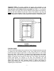
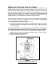
Important Note: To assure sufficient air supply and circulation to the condensing unit, a minimum clearance of 12" above the grill and 3" on each side and back of the cabinet must be provided (see figure 1). If necessary, special venting or air supply ducts must be installed by the installer for this purpose. Do not at any time obstruct the grill area in front of the cabinet in any way, and never place or store anything on top of the cabinet machine compartment.
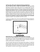
INSTALLING LEGS AND LEVELING REACH-IN MODELS Your new reach-in model is supplied with adjustable type legs for leveling purposes. Each single and two section model has four leg mounting holes on its case bottom, and three section models have six leg mounting holes. Legs are packed in the accessory carton from which they must be removed and installed on the cabinet case bottom (see figure 2).
Important Note: It is extremely important that your new reach-in or roll-in model is perfectly level for proper operation. If it is not level, the following adverse conditions will become apparent: 1. The door(s) will not be properly aligned and consequently will not provide a good seal. Roll-in door wiper(s) may bind. 2. Your model will run excessively due to improper door seal(s). 3.
INSTALLING CONDENSATE EVAPORATOR No floor drains or plumbing connections are required since all models use an automatic condensate water evaporating system. All designer line models utilize a unique hot gas condensate water evaporating system which is completely selfcontained and no further assembly or maintenance is required (these models are recognized by their evaporator coil which is located out of the food zone in an insulated plug-box housing next to the condensing unit).
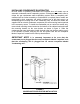
REMOVAL OF DOORS AND DOOR ADJUSTMENT During installation, it may become necessary to remove the cabinet doors to facilitate passage through narrow doorways or hallways. To remove a door, pry off all hinge covers using a sharp tool or knife (see figure 5). Swing the door to the open-door position (90 degrees) and carefully lift the door upward, removing the door from the hinge bodies.
REMOVAL OF GRILL To remove the grill, loosen all four (4) grill mounting screws located on the backside of the grill one or two turns. Simply lift grill up off of its mounting screws and out. To replace the grill, line up the grill mounting screws with the keyhole slots located on the cabinet body, push in on the grill and down.
START-UP PROCEDURE ELECTRICAL CONNECTIONS To insure proper operation, your new model must be connected to an individual circuit that can supply the full voltage as stated on the cabinet serial data plate. For correct voltage, power draw, and wire accommodations, check the data on the serial data plate located on the inner right wall of your new model. Verify that this information exactly matches the electrical characteristics at the installation location.
START-UP CHECKLIST After your model has been installed, leveled, cleaned, and electrically connected in accordance with this manual, please take the time before start-up to observe the following precautions to assure troublefree operation: 1. Check that all exposed refrigeration lines are free of severe dents or kinks. 2. Check the condenser fan and evaporator fans for freedom to rotate without any obstructions 3.
OPERATION All cabinets must be given sufficient time to reach normal operating temperature before placing any food inside. Refrigerators are designed to maintain an ideal cabinet temperature of 38`f to 40`f (3.3`c to 4.4`c) and approximately 2 hours of operation are required to reach this temperature. Standard freezers are designed to maintain an ideal cabinet temperature of -2`f to 0`f (-18.9`c to -17.8`c) and approximately 4 hours of operation are required to reach this temperature.
that many degrees by pressing directly on the mylar display towards the left bottom. Once calibration is complete return to normal temperature mode by pressing once again on the mylar display towards the right center. Now, recheck the calibration. Example: the digital display reads 45`f and the internal thermometer reads 40`f so, the digital display must be increased by 5`.
REFRIGERATOR SYSTEM AND ADJUSTMENT All self-contained value line and designer line refrigerators are designed and factory set to maintain an average cabinet temperature of 38`f. The temperature control is accessible from the top of the electrical console box located on the cabinet top behind the front grill (see figure 6).
FREEZER SYSTEM AND ADJUSTMENT All self-contained value line and designer line standard freezers and lowtemperature freezers are designed and factory set to maintain an average cabinet temperature of 0` f and -15`f respectively. All freezers are designed for the purpose of holding pre-frozen food and although they are capable of freezing small quantities of fresh food, they are not to be used as fast or blast freezers. Do not attempt to freeze bulk quantities of fresh foods.
After defrost, the fan delay control prevents the evaporator fans from operating until the evaporator coil has reached a temperature of 32°f (approximately 20 minutes) thus, minimizing warm air circulation inside the cabinet. Therefore, during initial start-up, and after each defrost cycle, the fans will not turn on immediately.
EVAPORATOR ASSEMBLY All value line and designer line refrigerators and freezers have an easily accessible, easily serviceable, performance rated, forced-air evaporator assembly which utilizes a plasticized fin coil for extended life.
PLUG-TYPE,TOP-MOUNT EVAPORATOR ASSEMBLY The plug-type evaporator system is a unique system in which the evaporator coil and air circulating fans are contained within a concealed plug-type insulated housing, readily accessible on the top of the cabinet and separate from the food storage zone. The entire plug system is fully charged with refrigerant and mounted on a steel rail type base which can be easily removed from the cabinet if a field conversion (refrigerator to freezer or vice versa) is desired.
INTERIOR REACH-IN ACCESSORIES The standard interior accessory package that is supplied from the factory with your new value line and designer line reach-in consists of standard pilaster strips with pilaster clips (four (4)clips per shelf), three (3) epoxy coated shelves per section, and four (4) epoxy coated shelves per section on glass door models only.
OPTIONAL INTERIOR ACCESSORIES In addition to the optional heavy-duty pilaster and clip as shown in figure 11b, aluminum and stainless steel angle pan slides and universal angle pan slides are available and shown in figure 12. Please consult the price list for additional interior and exterior options and accessories available from the factory for your model.
SAFETY PRECAUTIONS The following safety precautions should be followed when operating any appliances: ! Always disconnect the power cord before attempting to work on or clean any equipment. ! Disconnect the power cord when the appliance will be idled for a long period of time. ! Do not attempt to service this unit yourself as removing any covers may cause exposure to dangerous voltage. ! Always route the power cord so that it is not likely to be walked on or pinched by other appliances.
Precautions 1. Never use harsh detergents, cleaners, scouring powders, or chemicals when cleaning your model. 2. Strong bleaches tend to corrode many materials and should never come in contact with stainless steel. 3. Tincture of iodine, or iron should not come in contact with stainless steel. These solutions, which cause stainless steel to discolor, should be rinsed off immediately if contact occurs. 4.
If the condenser coil is dirty or blocked, disconnect the power supply to your model and using a stiff brush, brush the dirt from the condenser fins until the condenser is clear from any debris. Using a vacuum cleaner with a brush attachment may aid in this cleaning process. After cleaning, restore electrical service to your model.
TROUBLESHOOTING AND SERVICING GUIDE PROBLEM PROBABLE CAUSE CORRECTION Condensing unit will not start - no hum. 1.LINE DISCONNECTED, SWITCH OPEN. 1.CLOSE START OR DISCONNECT SWITCH. 2.REPLACE FUSE. 3.DETERMINE REASON AND CORRECT/REPLACE 4.RELOCATE CONTROL. 2.FUSE REMOVED OR BLOWN. 3.OVERLOAD PROTECTOR BLOWN. 4.CONTROL "OFF" DUE TO COLD LOCATION. 5.CONTROL STUCK IN OPEN POSITION. 6.WIRING IMPROPER OR LOOSE. Condensing unit will not start - hums but trips on overload protector.
PROBLEM PROBABLE CAUSE CORRECTION Condensing unit runs, but short cycles on: 1.OVERLOAD PROTECTOR. 2.THERMOSTAT. 3.HIGH PRESSURE CUT-OUT DUE TO: (a) INSUFFICIENT AIR SUPPLY. (B) OVERCHARGE. (c) AIR IN SYSTEM. 4.LOW PRESSURE CUT-OUT DUE TO: (a) VALVE LEAK. 1.SEE PROBLEM # 3. 2.DIFFERENTIAL MUST BE WIDENED. 3. (a) CHECK AIR SUPPLY TO CONDENSER. (b) EVACUATE AND RE-CHARGE. (c) EVACUATE AND RE-CHARGE. 4. (a) REPLACE, EVACUATE AND RECHARGE. (b) EVACUATE AND RE-CHARGE. (c) REPLACE EXPANSION DEVICE.
PROBLEM PROBABLE CAUSE CORRECTION Product zone temperature too high. 1.CONTROL SETTING TOO HIGH. 2.INADEQUATE AIR CIRCULATION. 1.ADJUST T-STAT 2.REARRANGE PRODUCT LOAD TO IMPROVE AIR CIRCULATION. 3.CLEAN CONDENSER COIL 3.DIRTY CONDENSER Suction line frosted or sweating. 1.OVERCHARGE OF REFRIGERANT. 2.EVAPORATOR FAN NOT RUNNING. 3.EXPANSION VALVE STUCK OPEN. 4.EXPANSION VALVE SUPERHEAT TOO LOW. Liquid line frosted, cold, or sweating. 1.RESTRICTION IN DRIER STRAINER. 2.
WIRING DIAGRAMS - 26 -
- 27 -
- 28 -
- 29 -
- 30 -
- 31 -
- 32 -
- 33 -
- 34 -