HYPER X PRODUCT ENHANCED COMPACT READER LMB_6000 and LMB_7000 INSTALLATION MANUAL Rédigé par / Written by : Philippe GOBRECHT Date : Signature : Approuvé par / Approved by : Bruno WIEDEMANN Date : Signature : Autorisé par / Authorized by : Philippe GOBRECHT Date : Signature / : Langue/ Language FR REFERENCE DU DOCUMENT / DOCUMENT REFERENCE Numéro / Number Code Doc. / Doc.
EVOLUTIONS SUCCESSIVES /SUCCESSIVE CHANGES INDICE / REVISION INDEX DATE MODIFIE PAR / CHANGED BY OBJET / DESCRIPTION A 06/2001 Ph. GOBRECHT Création B 09/2002 Ph. GOBRECHT Addition of FCC notice and CE Notice Langue/ Language FR REFERENCE DU DOCUMENT / DOCUMENT REFERENCE Numéro / Number Code Doc. / Doc. Code Indice / Revision Index 13053 108 CE DOCUMENT EST LA PROPRIÉTÉ DE BALOGH IL NE PEUT ETRE COMMUNIQUÉ À DES TIERS SANS AUTORISATION ECRTITE PRÉALABLE. THIS DOCUMENT IS BALOGH PROPERTY.
TABLE OF CONTENTS 1. FUNCTIONS AND PERFORMANCE ..................................................................................................................... 4 2. TECHNICAL CHARACTERISTICS....................................................................................................................... 5 3. THE POWER SUPPLY.............................................................................................................................................. 6 4.
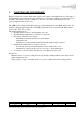
1. FUNCTIONS AND PERFORMANCE Hyper X system uses a reader which emits a microwave signal to an identification area . The range of this identification area varies from a few centimeters to several meters. When a tag enters this zone, it modulates this radiation, thereby sending its code back to the reader, which then processes the received signal and extracts the code. The LMB reader contains all the functional parts of the reading unit.
2.
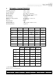
3. THE POWER SUPPLY The reader supply must be between 12Vdc and 24Vdc. With 12Vdc, the current is less than 1A With 24Vdc, the current is less than 0.6A The extreme limits for the power supply are 11Vdc to 28Vdc : it’s very important to respect these limits for correct operation of the readers and to avoid damage. A led « low voltage », near the power supply connector, indicates the voltage supply is less than 11Vdc.
4. VERIFICATION OF THE READER This verification is made during the powering on of the reader with all the interfaces and the inouts/Outputs disconnected.
5. INSTALLATION 5.1. LMB_6010 family The reader is made of a solid aluminium cast on which the circuits boards are fixed and a plastic radome fixed with two screws. To open the reader : - Unscrew and remove the two screws at each end of the reader - Remove the radome The reader must be mounted on a support (wall...) with 4 screws (maximum diameter is 6mm) at the corners of a rectangle of 151 x 241 mm. The procedure for closing the reader is the reverse of that for opening. 5.2.
6.
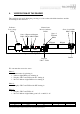
JK01 is a connector to measure the analog signal receive by the reader. These test points allow measuring the noise with a scope and therefore the quality of the electromagnetic environment for the installation. These test points allow measuring the analog signals from the tag. JT01 : is the connector for the supply voltage. A female connector with screw (Phoenix with 2 points pitch 5.08mm ref. MSTB 2,5/2-ST-5,08) must be used. JR01 : is the connector for the open collector output .
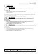
7. INSTALLATION AND CONNECTION PROCEDURES FOR THE ASYNCHRONOUS LINKS 7.1. Cable to be used for serial link RS422 or RS485 1. In a "clean" electromagnetic environment - twisted pairs, without screen. 2. In a "noisy" electromagnetic environment - twisted pairs, individual screen for each pair The cables are electrically characterised by : - characteristic impédance (Z0 in ohms) - distributed capacity (CL in pF/m).
Simplex wiring diagram: R L R : line-matching resistor, added if needed Half-duplex wiring diagram: R R L R : line-matching resistors, added if needed The length of the derivation should be as short as possible (< 30 cm). The maximum length allowed can be calculated from the cable characteristics using the equation below. L < 1300 / (Z0 x CL) L in metres, ZO in ohms and CL in pF 7.4.2.
8. OPEN COLLECTOR INTERFACE Both the ISO2 and the WIEGAND interfaces use an Open-collector interface. For correct operation, pull-up resistors (typical values are 1K) must be connected to any voltage supply between 5V and 12V. For the ISO2 interface, this concerns the three signals STROBE, MDATA and PRES_BADGE, for the WIEGAND interface this concerns the two signals DATA1 and DATA0. The pins are associated with different signals, depending on the type of link used. The JR2 connector is used.
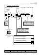
For the ISO2 system : 5 - 12 VDC 1K HYPERX READER O1 CLOCK O2 DATA O3 PRES_BADGE USER EQUIPMENT O5 0V For Wiegand system : 5 - 12 VDC 1K O1 DATA1 O2 DATA0 HYPERX READER USER EQUIPMENT O5 0V Langue/ Language FR REFERENCE DU DOCUMENT / DOCUMENT REFERENCE Numéro / Number Code Doc. / Doc. Code Indice / Revision Index 13053 108 CE DOCUMENT EST LA PROPRIÉTÉ DE BALOGH IL NE PEUT ETRE COMMUNIQUÉ À DES TIERS SANS AUTORISATION ECRTITE PRÉALABLE. THIS DOCUMENT IS BALOGH PROPERTY.
9. THE OUTPUTS (JR3) pin 1 2 3 4 5 6 name VI1 SIC1 SIE1 VI2 SIC2 SIE2 description Supply voltage for output 1 Collector output 1 Emitter output 1 Supply voltage for output 2 Collector output 2 Emitter output 2 . Détec te ur LMB V Ve xt < 24Vdc Ve xt (or Valim pin 4 of JR02) 1 k oh ms Rext SIC 10 0 o hm s O p to c oup le u r S ortie 10ko h m s le d jaune SIE GND The external voltage must not exceed 24Vdc Langue/ Language FR REFERENCE DU DOCUMENT / DOCUMENT REFERENCE Numéro / Number Code Doc.
10. THE INPUTS (JR4) pin 1 2 3 4 name EI1 GND1 EI2 GND2 description Signal for input 1 Reference for input 1 Signal for input 2 Reference for input 1 EI must not exceed 24Vdc. EI < 24Vdc Détecteur LMB 10kohms 1kohms Opto coupleur JR04 Pin EI Nom EI 1 GND 1 EI 2 GND 2 Entrée 1 1 2 3 Entrée 2 4 1kohms led jaune GND Langue/ Language FR REFERENCE DU DOCUMENT / DOCUMENT REFERENCE Numéro / Number Code Doc. / Doc.
11. OPERATING FREQUENCY CHANNEL The enhanced compact reader LMB can operate using 119 different channels (31 for Europe). Each channel corresponds to a separate microwave frequency band. This is useful when several readers must be positioned close together. Using different channels on each reader eliminates mutual interference. 119 channels are available (31 for Europe), the frequency band is between 2435.25MHz and 2464.75MHz (2446.25MHz and 2453.75MHz for Europe) with a channel spacing of 250KHz.
12. ADJUSTMENT OF THE READING RANGE All the readers are deliver with an adjustment with the maximum reading range. There are 4 positions for the adjustment : • Maximum reading range • Middle reading range • Minimum reading range • A few centimers. 12.1. Verification of the the position of the adjustment of the reading range : Push the red push-button "select" until the "Pr" is displayed. Then push the black button “display” once : the number corresponding to the reading range appears.
13. ORIENTATION OF THE ANTENNA LMB_6012 LMB_7012 90°x 90° LMB_6013 LMB_7013 90°x 90° LMB_7023 90°x 45° LMB_6033 LMB_7033 45° x45° LMB_6034 45° x45° LMB_6035 45° x45° Langue/ Language FR REFERENCE DU DOCUMENT / DOCUMENT REFERENCE Numéro / Number Code Doc. / Doc. Code Indice / Revision Index 13053 108 CE DOCUMENT EST LA PROPRIÉTÉ DE BALOGH IL NE PEUT ETRE COMMUNIQUÉ À DES TIERS SANS AUTORISATION ECRTITE PRÉALABLE. THIS DOCUMENT IS BALOGH PROPERTY.
1. FCC Notice This equipment has been tested and found to comply with the limits for a classB digital device, pursuant to Part 15 of the FCC rules. These limits are designed to provide reasonable protection against harmful interference in a residential installation. This equipment generates, uses, and can radiate radio frequency energy and, if not installed and used in accordance with the instructions, may cause harmful interference to radio communications.
14. CE Notice 0682 DECLARATION OF CONFORMITY BALOGH Toulouse 105 Avenue du Général Eisenhower 31023 TOULOUSE cedex 1 FRANCE This declaration that the following designated products LMB* comply with the essential protection requirements of R&TTE Directive 1999/5/CE on the approximation of the law of the Member States relating to Radio Spectrum Matters, EMC and Electrical safety.
Appendix 1 : General presentation HYP ER X ENHANCED COMPACT READER : LMB Red push-button Se lect/Sa ve Bla ck pus h-button Displa y/Change Bi-color led Bla ck push-button Rese t Low vo lta g e le d TTL link JR02 JK01 JT01 123 JR04 J R03 RS link JR01 1 2 3 4 51 2 3 4 5 12 34 1234 56 Inputs Outputs JK01 Buz z e r Display An a lo g m e a s ur em e n t JR01 : seria l link Pin Na me RS -2 32 RS -4 22 R S4 85 TX + +V 1 O1 TX -V 2 O2 TX --3 O3 RX + -RX 4 O4 RX -5 G ND G ND G ND G ND Pin Na me 1 I 2
Appendix 2 : Serial link SERIAL LINK : RS-232 RS232 Hyper X JR01 Reader PC COM port subD9 JR01 1 RS232 RX TX 2 2 HYPER X 3 READER 4 5 PC RX TX 3 GND 5 GND SERIAL LINK : RS-422 RS-422 JR01 PC Hyper X Reader JR01 1 TX+ TX2 HYPER X RX+ READER 3 RX4 5 RS-422 RX+ RXTX+ TX- PC GND Document ref. 6000X00X01 Langue/ Language FR REFERENCE DU DOCUMENT / DOCUMENT REFERENCE Numéro / Number Code Doc. / Doc.
CONFIGUR ATION o f EN HANCED COMPAC T REA DER : LMB AS YNCHRONU S S ER IA L LINK : RS 2 3 2 / 4 2 2 / 4 8 5 Pl e as e s ee the c on fig uratio n manual to get a d e tail e d l is t of all p os s i ble c o nfi gu ration s ☞ 1- s e le ct th e fu n c ti o n : red pu s h -b u t to n OP E RAT IN G MO DE Se le ct R e d a n d b la c k p u s h -b u t to n s are us e d to c o n f ig u re th e re a d e r.
Appendix 3 : Open collector output Connection to a WIEGAND system +5 to +12 Vdc JR02 1K 1K DATA1 DATA0 1 2 User Equipement HYPER X 3 READER 4 GND 5 Connection to an ISO2 system +5 to +12 Vdc JR02 1 HYPER X READER 2 3 1K 1K 1K STROBE MDATA PRES-BADGE User Equipement 4 5 GND The use of the third wire (PRESBADGE) is optional Langue/ Language FR REFERENCE DU DOCUMENT / DOCUMENT REFERENCE Numéro / Number Code Doc. / Doc.
CONFIGURATION OF EN HANCED COMPAC T REA DER : LMB OP EN COLLEC TOR INTERFACE WIE GA ND AND IS O 2 Pl e as e s e e th e c o nfi gurati on manual to g e t a de taile d li s t o f al l po s s ib le con fig uratio ns ☞ 1- s ele c t the fu nctio n : re d p u s h -b u tto n O P E RATING MODE Se le ct Re d an d b l a c k p u s h -b u tto ns a re u s e d t o c o n f ig u re th e re a d e r.
Appendix 4 : Inputs / Outputs HYP ER X ENHANCED COMPACT READER : LMB Co nfig u ra tio n o f OUTP UTS : c o n n e c to r JR 0 3 JR03 P in 1 O u tp u t 1 2 3 4 O u tp u t 2 5 6 N a me VI 1 S IC 1 S IE 1 VI 2 S IC 2 S IE 2 Ou tp u t 1 Not used ☞ Ch a ng e ☞ re a d. 100ms S e lec t LMB R e a d er VI hos t Ou put 2 S IC ☞ Sa ve ☞ ☞ Sa ve ☞ Ch a ng e Re x t 10 0 oh ms ☞ Ch a ng e Ve x t < 24 Vd c Ve x t (o r Va lim pin 4 o f J R02 ) 1 ko h m s ☞ Sa ve Ch a ng e rea ding.