
User's Manual
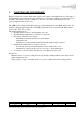
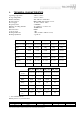
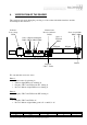
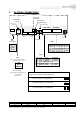
Table Of Contents
- 1. FUNCTIONS AND PERFORMANCE 4
- FUNCTIONS AND PERFORMANCE
- TECHNICAL CHARACTERISTICS
- THE POWER SUPPLY
- VERIFICATION OF THE READER
- INSTALLATION
- EXTERNAL CONNECTIONS
- INSTALLATION AND CONNECTION PROCEDURES FOR THE ASYNCHRONOUS LINKS
- OPEN COLLECTOR INTERFACE
- THE OUTPUTS (JR3)
- THE INPUTS (JR4)
- OPERATING FREQUENCY CHANNEL
- ADJUSTMENT OF THE READING RANGE
- ORIENTATION OF THE ANTENNA
- FCC Notice
- CE Notice

REFERENCE DU DOCUMENT / DOCUMENT REFERENCE
Langue/ Language Numéro / Number Code Doc. / Doc. Code Indice / Revision Index Pages
FR 13053 108 B
7/27
CE DOCUMENT EST LA PROPRIÉTÉ DE BALOGH IL NE PEUT ETRE COMMUNIQUÉ À DES TIERS SANS AUTORISATION ECRTITE PRÉALABLE.
THIS DOCUMENT IS BALOGH PROPERTY.IT CANNOT BE DISCLOSED TO ANY PARTY WITHOUT PREVIOUS WRITTEN AUTHORIZATION.
4. VERIFICATION OF THE READER
This verification is made during the powering on of the reader with all the interfaces and the
inouts/Outputs disconnected.
We can sume the successive states :
Phase 1 :
• Buzzer emits a bip during 1s
• Indicator light DR09 red on during 4s
• Displays UN17 and UN18 with “P1” during 4s
• Bi-color Indicator light DN02 red on during 5s
Phase 2:
• Displays UN17 and UN18 with “PE” during 1s
Phase 3 :
• Displays UN17 and UN18 off
• Bi-color Indicator light blinks green 0,5s on and 0,5s off.
JK01
JT01
JR04 JR03
JR02
1 2 3 4 5
JR01
1 2 3 4 5
1 2 3 4
Inputs
1 2 3
1 2 3 4 5 6
Outputs
TTL link
RS link
Displays
UN17 - UN18
Indicator
Low voltage
DT06
State of Inputs and Outputs
DR03 DR04 DR05 DR06
General state
Bi-color indicator
DN02
State of
TTL link
DR09
State of serial lin
k
DR07 DR08
Buzzer