234567890123456789012345678901212345678901234567890123456789012123456789012 1234567890123456789012345678901212345678901234567890123456789012123456789012 1234567890123456789012345678901212345678901234567890123456789012123456789012 1234567890123456789012345678901212345678901234567890123456789012123456789012 1234567890123456789012345678901212345678901234567890123456789012123456789012 1234567890123456789012345678901212345678901234567890123456789012123456789012 12345678901234567890123456789012123456789012345678
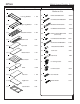
#27541 Part Drawing Mobile Laptop Charging Station Description Part Qty Drawing Description Qty Hardware List P-1 P-2 P-3 Left Leg Welded Right Leg Welded Slotted End Panel A Phil Screw M6X15mm 20 EA A1 CS Phil Screw M6X50mm 18 EA A2 Wood Screw M7x50mm 7 EA A3 CS Wd Screw M3x12mm 12 EA A4 Phil Pan Screw M4x12mm 4 EA 1 EA 1 EA 2 EA (Door Knobs) P-4 P-5 P-6 P-7 Middle Panel Top Panel Bottom Panel Back Panel A5 Pan Wd Screw M4x18mm 2 EA A6 Socket Screw M6x65mm 4 EA
Part Drawing P-12 P-13 Description 10 Outlet electrical Cord Wrap Part Qty Drawing Description Qty Hardware List 2 EA 2 EA J Lock Catch 1 EA K1 Lock Cylinder 2 EA K2 Lock Washer 2 EA K3 Lock Hex 2 EA K4 Lock Retainer 2 EA K5 ¼” Phil Head Lock Screw 2 EA L Key 4 EA M1 Grommet Sleeve 4 EA M2 Grommet Cap 4 EA N Allen Wrench 1 EA WARNING In order to charge all 20 laptops simultaneously, two separate 110-120 volt, 15-20 amp circuits are required.
#27541 Mobile Laptop Charging Station Assembly Diagram To Assemble: Illustration # 1 1.Identify and Separate all the Parts and Hardware. 2. Install 2 each Cam Posts (C2) in the 2 threaded G insert nuts in the Top Panel (P5) as shown in illustration #1. C2 P-5 3.Install 1 Wood Dowel (G) in the hole in the middle of the Top Panel (P5) C1 4.
.Attach Middle Panel (P4) to the Top Panel Illustration # 3 (P5) as shown in illustration #3. Secure by turning the Cam Locks (C1) 1/4 Turn until they lock. C2 P5 G 6.Attach Bottom Panel (P6) to the Middle Panel (P-4) using 2 Wood Screws (A2). P4 P6 C1 A2 To Secure Cam Locks, Insert Large Phillips Head Screwdriver and turn Cam Lock 1/4 turn (90 degrees) clockwise. 7. Place a Slotted End Panel (P3), large space at top, in the recess inside the Right Leg Welded (P2). .
Illustration # 5 P5 10.Slide 9 Shelves (P8) over Middle Panel (P4) and into slots in Slotted End Panel (P3) as shown in illustration #5. P8 P8 P6 Should you require assistance during assembly, please call our Customer Service Department Monday - Friday 8 a.m. - 5 p.m. Central Standard Time P4 Toll-Free Customer Service 1-800-749-2258 P3 A1 P3 P1 A1 P5 P8 11. Place Slotted End Panel (P3) over the end of 9 Shelves (P8) as shown in illustration #6. 12.
13. Place the Left Door (P9) with the Predrilled (for Hinges) holes facing up and Insert 1 each Lock Cylinder (K1) through the hole in the Left Door (P9) as shown in illustration # 7. Secure Lock Cylinder (K1) using the Lock Washer (K2) and the Lock Hex (K3). (FINGER TIGHTEN ONLY.) 14. Slide Lock Retainer (K4) over the square end of Lock Cylinder (K1). Secure using the ¼” Phil Head Lock Screw (K5). Illustration # 7 P9 K5 K4 A4 K3 F K2 15.
19. Press Grommet Sleeves (M1) in round openings in the Back Panel (P7) as shown in illustration #9. P7 Illustration # 9 M1 A P13 20. Attach 2 Cord Wraps (P13) to the Back Panel (P7) using 4 screws (A) and 4 Threaded Posts (B) as shown in illustration #9. B P7 A2 A2 A1 21. Attach Back Panel (P7) to the Left Leg Welded (P1), and the Right Leg Welded (P2) using 6 screws (A1) as shown in illustration #10. 22.
Illustration # 11 P11 P2 A6 D 23. Attach Caster Base (P11) to the Welded Legs (P1 & P2) using 4 each screws (A6) as shown in illustration #11. Tighten these 4 Screws using Allen Wrench (R). A 24. Attach 2 locking Casters (D) and 2 Inline Casters (E) to metal base (P-1)using 16 screws (A). Tighten Screws Allen Wrench (N) as shown in illustration #11. D A P1 A6 Illustration # 12 Note: Remove the plastic shipping caps to expose the outlet’s mounting holes. 9 25.
Illustration # 13 P3 26. Remove the plastic shipping caps off the second Electrical 10 Outlet (P12) and attach it to the Slotted Panel(P3) on the Right Side using 4 Screws (A5) as shown in illustration #13 P12 27. Route both electric cords acrooss the top shelf and through the 2 Grommet Sleeves (M1) in the Back Panel (P7) and out the back of the unit as shown in illustration #14. 28. Snap Grommet Cap (M2) over top of Grommet Sleeve (M1).
29. Attach Left Door (P9) to P9 Left Leg welded (P1) using 6 screw (A3) as shown in illustration #15. Illustration # 15 P1 30.Attach Lock Catch (J) to Middle Panel (P4) using 2 screw (A5) . 31. Attach Right Door (P10) to Right Leg Welded (P2) using 6 screw (A3) as shown in illustration #16 &16A. 32. Before tightening the Lock Hex (K3) on either door, insert the Key (L) and turn lock. Be sure that Lock Retainer (K4) turns 90 degrees and rotates behind Door Stop (J). TIGHTEN LOCK HEX (K3).