23456789012345678901234567890121234567890123456789012345678901212345678901234 123456789012345678901234567890121234567890123456789012345678901212345678901234 123456789012345678901234567890121234567890123456789012345678901212345678901234 123456789012345678901234567890121234567890123456789012345678901212345678901234 123456789012345678901234567890121234567890123456789012345678901212345678901234 123456789012345678901234567890121234567890123456789012345678901212345678901234 12345678901234567890123456789012123456
Odyssey High Capacity Charging Cart Part Drawing Description Part Qty Drawing Description Qty Hardware List P1 P2 P3 P4 Metal Base Top Panel Shelf Side Handle 1 EA 1 EA 2 EA A M6X15mm Socket Screw 40 EA A1 M6X45 mm Socket Screw 8 EA A2 M6X65 mm Socket Screw 4 EA B Grommet Metal Base 2 EA C Left Side Panel 4” Caster 2 EA F Allen Wrench 1 EA 2 EA 1 EA H I Right Side Panel P8 Back Panel Back Frame Cam 8 EA 12 EA 12 EA Wood Dowel 8 EA 1 EA K P7 Tapped Rivet
Odyssey Laptop Charging Cart Part Drawing Description Part Qty Drawing Description Qty Hardware List P10 P11 Center Back Panel Vertical Support 1 EA P Back Lock Q Lock Clip S Left Door 1 EA 2 EA R P12 1 EA Tablet Divider 54 EA Door Hinge 4 EA Hinge Screw-CS Wood 8 EA 1 EA T T1 Timer Mount Screw 4 EA #4 X 12mm P13 Right Door 1 EA U Hinge Screw-Door 8 EA V Divider Connector 54 EA W X P14 Vertical Hanging Bar 2 EA Y Z Key Sets Magnet Phillips Magnet Screws #4 X 2
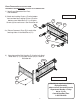
READ THROUGH INSTRUCTIONS FROM BEGINNING TO END BEFORE STARTING TO ASSEMBLE UNIT. 1.) Identify and Separate all the Parts and Hardware. Illustration # 1 2.) Attach two Locking Casters (C) to the bottom front and two Non-Locking Casters (D) to the bottom rear of Metal Base (P-1) using four Screws (A) for each caster. See Illustration #1. C Front A P-1 2a.) Place a Grommet- Base (B) in each of the two large holes in the Metal Base (P1). B D A 3.
4.) Attach the Left Side Panel (P5) to the Side Handle (P4) using four Screws (A1) and four Tapped Rivets (G) as shown in Illustration # 3. P-4 G P-5 Illustration # 3 A1 5.) Secure the Left Side Panel (P5) to the Metal Base (P1) using two Screws (A) as shown in Illustration # 4.
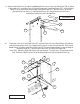
.) Screw in two Cam Posts (I) into the embedded plastic inserts in the Left Side Panel (P5) as shown in Illustration # 5. Install two Cams (H) into the large holes in the Back Panel (P7). Install a Wood Dowel (J) in the center hole on the edge of the Back Panel (P7). With the Cam’s (H) arrows pointed at the Cam Posts (I), slide the Back Panel (P7) into place and turn the Cams clockwise a quarter turn to the lock position. Illustration # 5 J I P5 P7 H 7.
8.) Screw in two Cam Posts (I) into the embedded plastic inserts in the Left Side Panel (P5) as shown in Illustration # 5. Install two Cams (H) into the large holes in the Back Panel (P7). Install a Wood Dowel (J) in the center hole on the edge of the Back Panel (P7). With the Cam’s (H) arrows pointed at the Cam Posts (I), slide the Back Panel (P7) into place and turn the Cams clockwise a quarter turn to the lock position. Illustration # 7 J H P5 P7 I 9.
10.) Attach the Right Side Panel (P6) to the Side Handle (P4) using four Screws (A1) and four Tapped Rivets (G) as shown in Illustration # 9. A1 G Illustration # 9 P4 P6 11.) Secure the Right Side Panel (P6) to the Metal Base (P1) using two Screws (A) as shown in Illustration # 10.
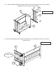
12.) Insert two Cams (H) into the top of the Left Side Panel (P5) making sure the arrow on the Cams (H) are pointed up. Press in two Wood Dowels (J) into the top edge of the Left Side Panel (P5). Screw in two Cam Posts (I) into the bottom left of the Top Panel (P2) as shown in Illustration # 11. Repeat these same Steps to install Cams(H), Wood Dowels (J) and Cam Posts (I) into the Right Side Panel (P6) and under the right bottom of the Top Panel (P2).
14.) Install the top Shelf (P3) in between the Left Side Panel (P5) and Right Side Panel (P6) using four Screws (A) into the threaded inserts in the side panels. Repeat this Step to install the bottom Shelf as shown in illustration #13. P5 P3 Illustration # 13 P6 A 15.) Attach the two Vertical Supports (P11) to the Top Panel (P2) and to the Metal Base (P1) using Screws (A) into the threaded holes as shown in Illustration #14.
16.) Attach two Door Hinges (S) to the Left Side Panel (P5) using four Hinge Screws -Wood (T) into the prdrilled locate holes for each hinge. Attach the Left Door (P12) to the Door Hinges (S) using two Hinge Screws-Metal (U) as shown in Illustration #15. P5 S U P12 T S U 17.) Illustration # 15 T Repeat Step 18 to install the Right Door (P13) to the Right Side Panel (P6) as shown in Illustration # 16.
18.) Attach the two Vertical Hanging Bars (P14) to the back of the two Shelves (P3) using one Electrical Mount Screw (L2) through an Electrical Mount (K) and into the threaded hole in the back flanges of the top and bottom shelves. Attach two more Electrical Mounts (K) using Electrical Mount Screws (L1) between the top an bottom Electrical Mounts on each Vertical Hanging Bar as shown in illustration #17. P3 Illustration # 17 P14 K L2 L1 L2 L1 19.
20.) Install nine Tablet Dividers (R) into each of the three slots in each Shelf (P3). Secure each Tablet Divider (R) to the Shelf from underneath by snapping on a Divider Connector (V). See illustration #19. R R V Detail Illustration # 19 21.) Install Magnet (X) under the Top Panel (P2) in the front center so it catches and holds the Left Door (P12) when it is closed. Use two Magnet Screws (Y) to secure. See illustration #20.
22.) Install the Electrical Tmer (Z) in the cut out at the boottom of the Right Side Panel (P6). Secure in place using four Timer Mount Screws (T1) as shown in illustration #21.
Odyssey High Capacity Charging Cart 50 1/4” 46 1/4” 24” 40” Shelf is 13 3/4” Deep 10 5/8” Clear 10 5/8” Clear 33” Clear 10 5/8” Clear 5 3/4” 27706_9-6-13 15