
Quick-Start Guide


4
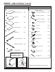
Illustration # 3
D
P-5
5.
6.
A
G
F
B
E
A1
P-6
P-1
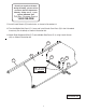
Be sure that arrow on
top of Camlock (C)
aligns with centerline of
Edge Drilled hole.
Phillips
Screwdriver
Centerline of
Edge Drilled
hole.
Arrow
8.
7.
9.
To Secure Cam Locks, Insert
Large Phillips Head Screwdriver
and turn Cam Lock 1/4 turn (90
degrees) clockwise.
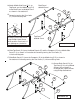
Place the Middle Side Panel (P-1) with the Camlocks(C)
facing up and install 2 each Cam Posts (D) in the 2
threaded insert nuts (Pre-installed) as shown
in illustration # 3.
Install 2 each Dowels (E) into the holes as shown in illustration # 3.
Attach Middle Side Panel (P-1) to Middle Leg (P-5 ) as shown in illustration
# 3. Secure by turning the Cam Locks (C) 1/4 turn until they lock.
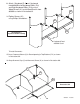
Attach Left Keyboard Slide (P-6) to the Middle Side Panel (P-1) using 2
each Screws (A1) as shown in illustration #3.
Attach 1 Glide Bracket (F) using 1 Socket Screws (A) and 1 Interior
Threaded Posts (B) as shown in illustration #3. Tighten Screws using
Phillips Screwdriver.
Insert 1 Glide (G) into the Glide Bracket (F) as shown in illustration #3.
P-1
D
C
Note: (B) screw
is in 1st HOLE
10.