IT0750-AB Owner’s Manual Mini Tie-Lok Tool IT0750 A B 0 0 Base part number 0 Other options: 0 – None (standard) 1 – Feedback system Product level Revisions are not compatible Trigger options: 0 – Standard thumb trigger 1 – Connection for a remote trigger (trigger not supplied) 2 – Tool with a foot/palm control Tool revision Revisions are compatible Packaging options: 0 – Tool with all accessories (standard) 1 – Tool only BAND-IT-IDEX, Inc. www.BAND-IT-IDEX.
IT0750-AB Table of Contents Mini Tie-Lok Tool Table of Contents Warranty & Safety Guidelines Page 3 Air System 4-6 Parts Identification 7,22 Tool Overview 8 Setup & Assembly Instructions 9-11 Remote Operations & Fixturing Tips 12,13 Operating Tips 14 Operating Instructions 15 Troubleshooting 16-20 Maintenance 21-28 Tension Cylinder Pressure Monitoring System 29-37 Tool Calibration BAND-IT-IDEX, Inc. 38 www.BAND-IT-IDEX.
IT0750-AB Warranty & Safety Guidelines Mini Tie-Lok Tool Warranty: For Warranty information visit the following URL www.BAND-IT-IDEX.com/Warranty.html Safety Guidelines • Read this manual and become familiar with the tool before installing any clamps. • Protective eyewear should be worn when connecting and disconnecting the tool to compressed air sources and during operation.
IT0750-AB Air System Mini Tie-Lok Tool The IT0750 is a pneumatic tool that needs a clean and dry air supply. The BAND-IT Air Controller Module includes a filter to meet these requirements. For proper tool performance, the air requirements at the inlet to the BAND-IT Air Controller Module of the IT0750 must be: Item Inlet Supply Pressure (PSI) Inlet Supply Air Flow (SCFM) Min Max 100 [690] 140 [965] 1.
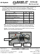
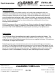
IT0750-AB Air System Mini Tie-Lok Tool Air Controller Module Inlet Air Supply Cut-off Air Outlet Tension Air Outlet Quick Disconnect Use one of two quick-disconnects supplied or remove and use 1/4” NPT fitting Air Shut-Off Valve Cut-off Air Pressure Gauge Exhaust Muffler Filter Fluid Drain Release Valve Cut-off Pressure Regulator Factory set to 105 PSI (725 kPa) Do not adjust Air Filter Environment: Standard Filters/Regulators incorporate polycarbonate bowls and/or observation windows.
IT0750-AB Air System Mini Tie-Lok Tool The standard IT0750 shipping container includes: Air Controller Module, IT0750 tool body, coiled air line, owner’s manual and tool kit. (tools with packaging option 1 include the tool and manual only) Pressure conversion: bar = kPa / 100 Initial Setup - Pneumatics • Connect the tool body to the Air Controller Module using the included Coiled Hose Assembly. The hose assembly includes both a clear and black hose.
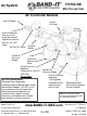
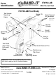
IT0750-AB Parts Identification Mini Tie-Lok Tool IT0750-AB Tool Body Tool Hanger Mounting Holes Model I.D. Plate Quick Connect Air Couplings (Do not add lubricants) Tension Cylinder Cut-off Cylinder Operating Trigger Serial # Location Reset Button Tool Head with Cutter Knife and Blade Quick Release Pins Maintenance Flip Cover Flip Cover Head Screws Flip Cover Tightening Screw Important: Before disassembling tool, be sure to shut-off air supply on the Air Controller Module. BAND-IT-IDEX, Inc.
IT0750-AB Tool Overview Mini Tie-Lok Tool Pneumatic System: The pneumatic valves and cylinders contain seals and o-ring components which can experience accelerated wear associated with quality of the supply. Worn cylinder o-rings allow air to bypass the pistons in the cylinders, affecting the performance of the tool and cause the output force of the tool to drift. Although cylinders are permanently lubricated, premature wear can be caused by contaminants in the air supply or the presence of water and oil.
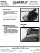
Setup & Assembly Instructions IT0750-AB Mini Tie-Lok Tool Handle adjustment: • Using 1/4” hex key (supplied), adjust the Support Arm/Handle to ergonomically match the operators hand. • Be sure not to adjust the Handle too far outward (beyond interlocking legs) or the handle will not function properly or provide support to the operator. Hanger Support Instructions: 1. An aluminum hanger (accessory option) can be utilized for supporting the tool. 2.
Setup & Assembly Instructions IT0750-AB Mini Tie-Lok Tool Fixture Locating Points Fixture Mounting Locations Three additional fixture mounting holes are available to assist with mounting the IT0750. Thread size is #10-32 for each of the holes. Usable thread depth is .400” for two of the three fixture holes. One hole is utilized to attach and lock the tool body halves together.
Setup & Assembly Instructions IT0750-AB Mini Tie-Lok Tool Part of insuring that the tool is producing a strong lock is making sure that it approaches the application correctly and is fixtured to allow repeatability of application. The tool should approach the surface tangent to where the buckle of the band is to be applied. The tool should be allowed to float 1/8” – 1/4” above the surface to allow the buckle to move to the proper position for cut-off.
IT0750-AB Remote Operation & Fixturing Tips Mini Tie-Lok Tool IT0750 Orientation Requirements: • The IT0750 tool has a number of Tool/Clamp/Object Being Clamped orientation requirements that must be followed in order to reach an acceptable end result.
IT0750-AB Remote Operation & Fixturing Tips Mini Tie-Lok Tool IT0750 Configured for Remote Actuation: • The IT0750 with trigger option 1 and is a modified version of the base unit. A tool with trigger option 0 is manually operated via the incorporated thumb actuation lever. A tool with trigger option 1 is configured to allow remote operation via palm button or other device permitting the tool to be incorporated into the customer’s fixture or assembly process.
IT0750-AB Operating Tips Mini Tie-Lok Tool Clamp Installation: When installing a clamp, a random visual check to verify the presence of a locking dimple after the clamp has been applied is recommended. The dimple is the locking element of an installed band. The IT0750 forms a dimple into the band in the buckle area with the knife.
IT0750-AB Operating Instructions Mini Tie-Lok Tool 2.5” 1. Insert clamp tail into tool as shown. Clamp tail length extending into tool must be at least 2.5” (6.4 cm) long. The head of the tool should rest against the buckle. Note - Do not activate tool while inserting clamp tail. This can cause clamp tail to jam in the Tension Block Assembly. 2. Begin tensioning clamp by pushing and holding down operating trigger 3.
IT0750-AB Troubleshooting Mini Tie-Lok Tool Tool fails to fully tension clamp: Failure to fully tension the clamp can be caused by a variety of factors. The two most common factors are: incorrect tension pressure and problems in the Tension Block Assembly. • Check tension pressure setting on Tension Pressure Gauge of Air Controller Module. Adjust pressure per the settings in the Setup & Assembly Instructions section found on (pages 9-11).
IT0750-AB Troubleshooting Mini Tie-Lok Tool Tool fails to cut off clamp tail: • The Inlet Air Pressure may be low. Check air supply to Air Controller Module. Cut-off Pressure Gauge should indicate 100-110 PSI (690-760 kPa). See pages 4 - 6 for air supply requirements. • The scrap clamp tail from the previous clamp may not have been removed. Press the Reset Button to release the tension on the clamp and remove the scrap clamp tail. • The Cutter Blade or Knife may be worn.
IT0750-AB Troubleshooting Matrix Symptom Tool will not tension properly (i.e. slipping, slow etc.) Probable cause Mini Tie-Lok Tool Recommended Fix Page Rear tension block slipping, Remove and inspect gripper block assembly. Replace as therefore tool does not required. reach cut off tension. Front gripper slipping Remove and inspect front gripper and gripper guide arm. Replace if worn. Dirty front and rear gripper Remove and clean contact surfaces surrounding grippers.
IT0750-AB Troubleshooting Matrix Symptom Probable cause Tool will not cut Linkage components off clamp tail - damaged, causing Continued. interference Cut-off cylinder seal damaged or leaking Cut off pneumatic air leak Loose clamp after cut-off Recommended Fix Page Remove tool left side body and verify linkage mechanism. Remove and replace damage as required or contact BANDIT. Remove left side tool body and verify seal integrity 27 * Verify Coiled Hose Assembly is free of air leaks.
IT0750-AB Troubleshooting Matrix Symptom Clamp will not insert into tool Probable cause Control Module air pressure valve is in "off" position. Clamp tail inside tool Knife is in down position. Handle will not adjust Mini Tie-Lok Tool Wrong clamp type for tool Handle nut is damaged/misaligned. Recommended Fix Page Rotate Control Module valve to open position. Verify gauges read air pressure and check all air connections.
IT0750-AB Maintenance Mini Tie-Lok Tool Tool Preventative Maintenance: The tool has some wear components that must be checked and replaced on a certain schedule. BAND-IT has developed a Preventative Maintenance (PM) schedule to help facilitate these requirements. If tools are experiencing difficulties during function or there audible air leaks coming from inside the handle, the tool should be returned to BAND-ITIDEX, Inc. for servicing.
IT0750-AB Maintenance Mini Tie-Lok Tool Production tools will experience wear of specific parts. Preventative maintenance, including regular cleaning and lubrication, will reduce the replacement frequency of these parts. To maximize life, use synthetic gel lubricant containing Teflon. See (pages 23-28) for tool maintenance. When repairing tools, threaded fasteners should be secured using a small amount of Loctite, Blue - Medium strength being careful to apply sparingly.
IT0750-AB Maintenance Mini Tie-Lok Tool Knife Assembly Replacement: A) Remove Cutter Blade as described on page 17. B) Remove the 2 Knife Pin Access Screws. These are special length screws. Important: When repairing tools, threaded fasteners should be secured using Loctite, Blue - Medium strength. To remove Cutter Knife Pin the Knife Assembly must be in its uppermost position indicated by the Cutter Knife Pin in line with the access hole. If not aligned, connect the tool to the Air Controller Module.
IT0750-AB Maintenance Mini Tie-Lok Tool Tension Block Assembly Maintenance: Remove the Maintenance Flip Cover by loosening the Maintenance Cover Tightening Screw and Head Screws on the Maintenance Flip Cover and removing both Quick Release Pins as shown on page 17.
IT0750-AB Maintenance Mini Tie-Lok Tool • Remove the Maintenance Flip Cover. Examine all moving parts and linkages for wear. • Using an air nozzle, gently clean the parts of any dirt and metal filings in the tensioning cavity. • Using cotton swabs or a short bristled brush, continue to wipe away any foreign debris and purge once again with the air nozzle. • After thoroughly cleaning all moving parts, re-lubricate all surfaces. Following are lubrication instructions.
IT0750-AB Maintenance Mini Tie-Lok Tool 4) Lubricate the removed cover as shown with red arrows above. Also, lubricate the tool body, linkage and Tension Block Assembly as shown on page 27. 5) Inspect all mechanical linkage for lubrication, proper placement and refit cover. 6) Secure the tool side cover by inserting and tightening (2) #10 – 32 X 4” length cap screws through the Cylinder Housing and into the Cover.
IT0750-AB Maintenance Mini Tie-Lok Tool Lubrication – Follow recommended intervals – Use a synthetic gel lubricant containing Teflon for the internal parts as shown and described. Lubricate all pivot points and internal surfaces of maintenance flip cover with a light coating of the lubricant. Caution – Excessive amounts of lubricant may result in gripper slippage, requiring a full repeat of cleaning process.
IT0750-AB Maintenance Mini Tie-Lok Tool Procedure to adjust the timing of the clamp tail cut-off: The Timing Valve will be affected over time by contaminants in the air system. Moisture, dirt particles, oil and solvents can cause blockage or fluctuations in the tool performance. Cycle should be .5 – 1.0 seconds. Cut-off timing set too short will not allow the clamp to achieve the desired tension before switching to the cut-off function causing a loose clamp.
Tension Cylinder Pressure Monitoring System IT0750-AB Mini Tie-Lok Tool The tension feedback system provides an indication, but not confirmation, of clamp tail tension by transmitting a pressure reading from the tension cylinder via a pressure transducer. The cut-off cylinder begins to move when the tool has reached maximum tension. The force applied by the tension cylinder is calculated from the transducer signal. The transducer signal is recorded when the cut-off cylinder begins to move.
Tension Cylinder Pressure Monitoring System IT0750-AB Mini Tie-Lok Tool Overview of Data Control Box Red indicator: • Reading out-of-range • Wrong tool version connected Yellow indicator: • No tool connected • Error in cut-off cycle Button: • Resets relay 1 • Program change (hold for 3 seconds) Green indicator: • Ready to monitor tool • No errors Relay contacts 12VDC 500mA max Relay1, closes on: • Out-of-range reading Relay2, closes on: • Clamp cycle completion BAUD selection switch BAND-IT-IDEX, In
Tension Cylinder Pressure Monitoring System IT0750-AB Mini Tie-Lok Tool Setting the upper and lower control limits Included in the CD provided with the tool is a program that can be used to adjust the type of data and the upper and lower control limits that the control box will monitor. 1. 2. 3. 4. 5. 6. 7. Connect the control box to power and to a device that will allow 2-way RS232 communication such as a PC with HyperTerminal. For this procedure flow control must be disabled.
Tension Cylinder Pressure Monitoring System IT0750-AB Mini Tie-Lok Tool Specifications: • • • • • • • • Power: 110-240 50-60 Hz VAC input, 5VDC output wall supply adapter (6 ft wire provided) Pressure range: will detect 10 to 125 PSI (70-860 kPa) Output: 9-pin RS-232 serial (approx 10 ft cable provided) Serial settings: o 2400 or 9600 Baud o 8 bit o No parity o 1 stop bit o ASCII formatted data o No flow control Data format: Data columns (clamp number, PSI, estimated LBF and error if any) separated by t
Tension Cylinder Pressure Monitoring System IT0750-AB Mini Tie-Lok Tool Data Capture: • • • • The tension feedback system can be used with many data capturing devices including any computer with Windows operating software. Any properly equipped tool will work with any I75390 data control box. The tool’s serial #, clamp count and settings remain with the tool and will be detected by any control box used.
Tension Cylinder Pressure Monitoring System IT0750-AB Mini Tie-Lok Tool Trouble Shooting Guide for the Tension Feedback System: No data output: Is power connected? Is the tool connected with a CAT5 patch cable? Is the control box connected using a RS-232 serial cable? Null modem cables will NOT work with this device. Some computer systems’ ports, to which the control box is connected, may be in use by another program. Close the program or try another port.
Tension Cylinder Pressure Monitoring System IT0750-AB Mini Tie-Lok Tool Cut-off Timing Verification Procedure 1. This procedure requires the use of the M28090 Calibration Device. 2. Prepare tool by connecting the M28090 Calibration Device per instructions included with the device. 3. To switch the breakout box over to check cut-off timing, press and hold the button on the control box 3-4 seconds.
Tension Cylinder Pressure Monitoring System IT0750-AB Mini Tie-Lok Tool Connections: 1. Data cable connection between tool and breakout box: 8-pin, 15 ft long, CAT5e cable provided. This cable carries 5 VDC power and 5 digital lines. Using a cable longer than 15 ft will degrade the signal and may cause the tool to incorrectly report pressure readings. Only connect the data control box to the tool. Never connect either the tool or control box to any other device.
Tension Cylinder Pressure Monitoring System IT0750-AB Mini Tie-Lok Tool (Example of data collection using a Windows XP Operating System) 1. Begin with Start Menu:\Programs\ Accessories\Communications\HyperTerminal 2. Type a connection name. 3. Click OK 6. Properties dialog box appears 7. Port Settings should be: • Bits per second (2400 or 9600) • Data bits (8) • Parity (None) • Stop bits (1) • Flow control (NONE) Click OK 4. “Connect to” dialog box appears 5.
IT0750-AB Tool Calibration Mini Tie-Lok Tool BAND-IT’s use of the word calibration refers to the tool’s electronic output being checked against a load measuring device. This is to insure that the electronic calculation of the output force based on the supply pressure is still matched up with the actual output force of the tool. To measure the actual output of the tool, BAND-IT has developed a Calibration Device (M28090). Call BAND-IT for more information.