
Operation Manual

31
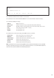
GPS input
gps1.d; gps2.d
The gpsX.d les dene the inputs of GPS units and the location of the antenna relative to the bow of the yacht.
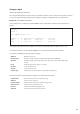
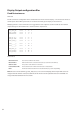
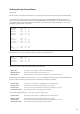
An example of a GPS conguration le is shown below:
Channel 1
Device 1
Com 1 RS232 19200 N 8 1
Offset 0.0
Bow 55.0
COG 100 null.cal null.l null.alm
SOG 101 null.cal null.l null.alm
QHD 102 null.cal null.l null.alm
SVA 103 null.cal null.l null.alm
UTC 104 null.cal null.l null.alm
Line 1 denes the CAN Channel the module is connected to.
Line 2 denes the Device ID of the Module (NOTE: this is set via the DIP switch inside the module).
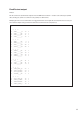
Line 3 denes the COM port settings:
COM Port COM port used [1 or 2]
Hardware Type Hardware settings for the type of data [RS232, RS485, RS422, NMEA0183]
Baud Rate Baud Rate setting to suit the input [4800, 9600, 19200, 28800, 38400, 57600, 115200]
Parity Parity setting to suit the input[N = no parity]
Data Bits To suit the input [7 or 8]
Stop Bits To suit the input [1 or 2]
Compass Type Identies special compass types (see compatible compass types)
Line 4 denes the GPS antenna position:
Oset GPS Antenna oset from centreline ( - Port, + Starboard) in feet
Bow to GPS GPS Antenna distance from Bow in feet
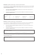
The additional lines dene the variables. Normally this should not be changed though, for example, you may
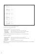
wish to add a link to a lter le for SOG:
Variable Name Name of the variable, for user information only]
COM Port Same port as line 3 (above)
Variable Number Variable number where data is stored (from bg_vars.d)
Calibration File Filename of the calibration le to use
Filter File Filename of the lter/damping le to use
Alarm File Filename of the alarm le to use [optional]
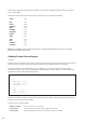
Note: For NMEA0183 GPS inputs the preferred inputs are as follows:
Position: GGA, GLL (If GGA or GLL is not available then RMC can be used for Position, in this case VTG must be disabled.)
Velocity: VTG