
Installation Manual


6
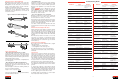
Problem Cause Solution Problem Cause Solution
V Belts
Rapid failure with no
visible reason
Replace sheavesWorn sheave grooves
(Check with groove
gauge)
Replace all belts with
a new set, properly
installed
Tensile cords damaged
through improper instal-
lation
Redesign driveUnderdesigned drive
Replace all belts with
correct type, properly
installed
Wrong type or cross
section belt
Dry, hard sidewalls.
Low adhesion between
plies. Cracked belt bottom
Remove heat source.
Improve ventilation
High temperature
Deterioration of rubber Don’t use belt dress-
ing. Clean belts and
sheaves with degreas-
ing agent or detergent
and water. Tension
belts properly
Belt dressing
Replace sheavesWorn or damaged
sheaves
Broken belts Shield driveForeign object in drive
Spin burns Retension driveBelts slip under starting
or stalling load
Redesign driveSheave diameter too
small
Redesign driveLoad miscalculated –
drive underdesigned
Cracked bottom Redesign driveSheave diameter too
small
Replace with an inside
idler on slack side, or
redesign
Back side idler too small
Retension driveSlippage
Remove heat source.
Improve ventilation
High temperature
Extreme cover wear,
worn corners
Remove obstruction
or realign drive
Belt rubs against guard
or other obstruction
Retension driveImproper tension
Clean belt, shield driveDirt on belt
Repair or replace
sheaves
Sheaves rusted, sharp
corners or burrs on
sheaves
Align sheavesSheaves misaligned
Short Belt Life
Use Bando Combo
belts
Shock loads
Position idler on slack
side of drive, as close
as possible to driveR
sheave
Incorrectly placed flat
idler pulley
Install idlerDistance between
shafts too long
Replace with Bando
®
belts
Belt lengths uneven
Retension driveBelts too loose
Belt Vibration
Use Bando Combo
belts
Severe vibration and
shock loads
Shield driveForeign material in
grooves
Realign sheavesMisaligned sheaves
Replace sheavesWorn sheave grooves
(Check with groove
gauge)
Replace all belts with
a new set, properly
installed
Tensile cord broken
from improper installa-
tion
Retension driveBelt undertensioned
Position idler on slack
side of drive, as close
as possible to driveR
sheave
Incorrectly placed flat
idler pulley
Belt Turnover
Troubleshooting Guide
Redesign driveSheave diameter too
small
Shield the driveForeign substance
caught between belts
and sheave
Soft, slick, swollen
sidewalls. Low
adhesion between
plies
Clean belts and
sheaves with degreas-
ing agent or detergent
and water. Remove
source of oil or grease
Oil or grease on belt or
sheave
Cut bottom Check tension and
alignment
Belt ran off sheave
Shield driveForeign object in drive
Replace all belts with
a new set, properly
installed
Improper installation
Belts stretch unequally Realign driveMisaligned drive
Replace all belts with
a new set, properly
installed
Tensile cord broken
from improper installa-
tion
Belts stretch equally Check take-up and fol-
low guidelines
Insufficient take-up
allowance
Redesign driveOverloaded or underde-
signed drive
Belt Stretch
RetensionBelt slip
Realign sheavesMisaligned sheaves
Replace cut edge
with wrapped belt
Wrong belt type
Belt Noise
Retension driveSpin burns
Redesign driveToo few belts
Severe Slippage
3
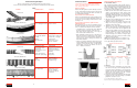
Force/deflection method
1. Measure the span length “L” of your drive (see Figure 1).
2.At the center of the span, apply a force perpendicular
to the belt. Measure the force required to deflect the
belt 1/64" per inch of span length. For example, for a
100" span, the deflection would be 100/64", or approx-
imately 1 1/2 inches.
3.Compare the force required to the recommended
ranges in the tables below. Tighten or loosen the belt
to bring it into the recommended range.
4.When you install new belts, tighten them to “initial ten-
sion” forces shown in the tables. This tension will drop
during the run-in period.
Inspect belt drive in 24-48 hours
During the 24-48 run-in period, the initial stretch is taken
out of the belts and the belts seat lower in the sheaves.
Check belt tension to assure it falls between the maxi-
mum and minimum values shown in the tables to the
left.
Belt Storage Tips
Under proper conditions, belts can be stored for many
years without shortening service life. Follow these
guidelines:
• Store belts in a cool, dry, dust-free area, away from
radiators and direct sunlight. Temperatures below 85°
and relative humidity below 70% are recommended.
• Store belts away from ozone producing unguarded flu-
orescent lights, mercury vapor lights, and high voltage
electrical equipment.
• Don’t store belts near chemicals, oils, solvents, lubri-
cants, or acids.
• Belts can be coiled on shelves or hung on pegs. Avoid
sharp bends and stresses that can cause permanent
deformation and cracks. Stack belts no higher than
12" to prevent damage to bottom belts. When hanging,
coil longer belts to prevent distortion from belt weight.
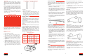
Synchro-Link
®
Timing Belt Drives
Installation
Inspect timing belt pulleys for dirt, rust, damage, and
wear. Clean pulleys as needed; replace worn or dam-
aged pulleys.
Check that the pulley support structure is rigid. Loose
supports cause center distance variation, shaft mis-
alignment, and pulley-tooth disengagement.
Check drive alignment with a straightedge and make
sure pulleys and shafts are parallel. On a long-center
drive, it’s often advisable to slightly offset the driveN pul-
ley to compensate for the belt’s tendency to run against
one flange of the driveR pulley.
Never force or pry a belt over the pulley flange. Reduce
center distance or idler tension, or remove one or both
pulleys. Lay the belt over the pulleys and adjust the take-
up until the belt teeth mesh securely with the pulley
grooves.
Note: For banded belts, multiply the force in the table by the number of belts in the band.
* 1/2 of this deflection force can be used, but substitute deflection amount as follows:
DA (inches) =
LS (inches)
128
- 3.0 3.6 3.1 2.4
3.1 - 4.0 4.2 3.6 2.8
4.1 - 5.0 5.2 4.6 3.5
5.1 - 6.1 5.3 4.1
- 4.6 7.3 6.4 4.9
4.7 - 5.6 8.7 7.5 5.8
5.7 - 7.0 9.3 8.1 6.2
7.1 - 10.0 8.8 6.8
- 7.0 12.5 10.7 8.2
7.1 - 9.0 15.0 13.0 10.0
9.1 - 12.0 18.0 16.3 12.5
12.1 - 19.5 16.9 13.0
12.0 - 13.0 25.5* 22.1 17.0
13.1 - 15.5 30.0* 26.0* 20.0
15.6 - 22.0 32.0* 28.0* 21.5
18.0 - 22.0 45.0* 39.0* 30.0*
22.1 - 52.5* 45.5* 35.0*
1.5 - 2.0 1.4 1.1 0.8
2.1 - 2.7 1.9 1.4 1.1
2.8 - 4.0 2.5 2.0 1.5
2.0 - 2.5 2.1 1.6 1.2
2.6 - 3.5 2.4 1.8 1.4
3.6 - 5.0 3.1 2.3 1.8
3.0 - 3.5 3.2 2.5 1.9
3.6 - 4.5 4.1 3.2 2.4
4.6 - 6.0 5.1 3.9 3.0
- 3.0 5.1 4.4 3.4
3.1 - 4.0 5.5 4.8 3.7
4.1 - 5.0 6.0 5.2 4.0
5.1 - 6.7 5.9 4.5
- 4.6 10.0 8.7 6.7
4.7 - 5.6 11.0 9.5 7.3
5.7 - 7.0 11.5 9.9 7.6
7.1 - 12.0 10.1 7.8
- 7.0 18.0 15.6 12.0
7.1 - 9.0 19.5 16.9 13.0
9.1 - 12.0 20.0 17.6 13.5
12.1 - 21.0 18.2 14.0
2.65 - 3.35 4.6 4.0 3.1
3.65 - 4.50 5.5 4.8 3.7
4.75 - 6.0 6.4 5.6 4.3
6.5 - 10.6 7.3 6.4 4.9
7.1 - 10.3 16.5 14.3 11.0
10.9 - 11.8 19.5 16.9 13.0
12.5 - 16.0 21.0 18.2 14.0
12.5 - 16.0 39.0* 33.8* 26.0*
17.0 - 20.0 45.0* 39.0* 30.0*
21.2 - 24.4 51.0* 44.2* 34.0*
2.2 - 2.5 4.8 4.2 3.2
2.65 - 4.75 5.7 4.9 3.8
5.0 - 6.5 7.2 6.2 4.8
6.9 - 8.7 7.5 5.8
- 5.5 15.0 13.0 10.0
5.9 - 8.0 19.0 16.9 13.0
8.5 - 10.9 21.0 18.2 14.0
11.8 - 22.0 19.5 15.0
Recommended Deflection Force (Lbs.)
V-Belt
Cross
Section
A
B
C
D
E
3L
4L
5L
AX
BX
CX
3V
5V
8V
3VX
5VX
Small Sheave
Diameter Range
(Inches)
Initial
Installation
Retensioning
Maximum Minimum
V-Belt Tensioning
Figure 1
Rapid sidewall wear Replace sheavesWorn or damaged
sheaves