
Installation Manual


Belt Size 012 019 025 031 037 050 075 100 150 200 300 400 500 600
Belt Width
1
/8"
3
/16"
1
/4"
5
/16"
3
/8"
1
/2"
3
/4" 1" 1
1
/2" 2" 3" 4" 5" 6"
MXL
Max. .10 .15 .24 .35 .42 .62
Min. .05 .09 .13 .19 .22 .33
XL
Max. .42 .55 .66 1.1 1.9
Min. .20 .31 .37 .57 1.0
L
Max. 1.3 2.1 2.9 4.7 6.4
Min. 1.0 1.5 2.2 3.4 4.7
H
Max. 4.7 6.8 10.4 14.3 22.4
Min. 3.7 5.2 8.2 11.2 17.6
XH
Max. 17.7 27.9 39.7 51.0 62.2
Min. 16.3 25.8 36.7 47.0 57.3
XXH Max. 40.5 63.9 90.7 117.2 142.1
Min. 21.5 34.0 48.1 62.3 75.2
4 5
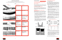
Tensioning
Timing belts should fit the pulleys snugly — neither too
tight nor too loose. The “tooth grip” principle eliminates
the need for high initial tension. A snug belt-pulley fit
extends belt and bearing life, and gives quieter opera-
tion.
Measure span length (“L” in Figure 2 below) and apply a
force perpendicular to the belt. Measure the force
required to deflect the belt 1/64" per inch of span length.
Compare the force required with the table below and
tighten or loosen the belt as required, to bring it into the
recommended range.
For example, an H pitch belt, 1" wide with a span of 30",
should take a force of 5.2-6.8 lbs. to deflect the belt
30/64", or about 1/2".
Taper-Lock
®
Pulleys
To install:
1. Place bushing in the pulley.
2. Apply oil to both the thread and the point of
setscrews. Place screws loosely in pull-up holes.
3. Make sure the bushing is free in the pulley. Slip the
assembly onto the shaft and position it for proper
belt alignment.
4. Tighten the screws alternately and progressively
until they are tight. To increase leverage, use a
wrench or length of pipe.
5. Tap the large end of the bushing (use hammer and
block or sleeve to prevent damage). Tighten the
screws to the torque values shown in the following
table. Fill the other holes with grease to keep dirt
out.
Torque Values for Tightening TL
®
Bushings
TL
®
Bushing Wrench Torque (In. Lbs.)
TL1008 . . . . . . . . . . . . . . . . .55
TL1210 . . . . . . . . . . . . . . . .175
TL1215 . . . . . . . . . . . . . . . .175
TL1610 . . . . . . . . . . . . . . . .175
TL1615 . . . . . . . . . . . . . . . .175
TL2012 . . . . . . . . . . . . . . . .280
TL2517 . . . . . . . . . . . . . . . .430
TL3020 . . . . . . . . . . . . . . . .800
TL3535 . . . . . . . . . . . . . . .1000
TL4040 . . . . . . . . . . . . . . .1700
To remove:
1. Remove both setscrews.
2. Apply oil to both the thread and point of one
setscrew. Insert this screw in the tapped removal
hole, and tighten the inserted screw until the bush-
ing is loose in the sheave. (Note that one setscrew
is not used for removal.)
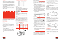
Rib Ace
®
Drives
Installation
Clean rust and dirt from Rib Ace
®
sheaves; replace worn
or damaged sheaves. Sheave alignment is very impor-
tant, and should be checked with a straightedge as
shown on page 2.
Never force or pry a Rib Ace
®
belt over the sheaves.
Reduce the center distance and lay the belts over the
sheaves.
Tensioning
Measure span length (“L” in illustration below) and apply
a force perpendicular to the belt. Measure the force
required to deflect the belt 1/64" per inch of span.
Multiply the number of ribs by the force “F” per rib in the
chart below, compare this to the force required, and
loosen or tighten the belt as needed.
Run the drive briefly to seat the belt, and recheck the
tension. At least one sheave should be freely rotating
during the tensioning procedure.
Quarter Turn Drives
Quarter turn V-belt drives are used to transmit power
from a horizontal shaft to a vertical shaft, or vice versa.
For maximum service on these drives, follow these
guidelines:
1. Deep groove sheaves should always be used. Use
individual — not banded — belts.
2. Center distance should be equal to 5 1/2 times the
sum of the diameter of the large sheave plus its
face width. This long center distance is necessary
to insure the entry angle of the belts into the
sheave grooves is 5° or less.
3. Speed ratio should not exceed 2.5:1. Greater
speed ratios require such long center distances
that a two-stage drive may be more feasible.
4. The center line of the horizontal shaft on the quar-
ter turn drives should be above the center of the
vertical shaft sheave.
V-Flat Drives
Usually a converted flat belt drive, a V-flat drive has one
V-grooved sheave and one flat pulley. For best results,
follow these recommendations:
1. The arc of contact, or belt wrap, determines if a V-
flat drive is practical. Use the formula A= , where
D is the large sheave diameter, d is the small
sheave diameter, and C is the center distance. If A
is between 0.5 and 1.5, the V-flat drive will have
sufficient wrap to transmit the load under the prop-
er tension.
2. The flat pulley should have a straight face for best
operation. If the pulley is crowned, it should not
exceed 1/4" per foot (on the diameter) of face
width. When possible, remove the crown by
machining.
3. Shock loads and/or pulsating loads should be
avoided on V-flat drives.
4. Bando Combo (banded) belts are ideally suited for
V-flat drives. Power King
®
belts may also be used.
Consult Bando if Power Ace
®
belts are considered
for use on V-flat drives.
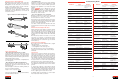
Idlers
V-Belt Idlers
An idler is a grooved sheave or a flat pulley that does not
transmit power. Idlers create additional bending stress-
es within a belt, and thus reduce horsepower ratings.
Take this into account during drive design so belt life
isn’t reduced.
Idlers are generally used under these circumstances:
• To tension and provide for take-up on a fixed center
drive
• To dampen vibration in a long belt span
• To increase the arc of contact on a small sheave so
the belt won’t slip
• To guide belts around obstructions and to turn corners
• To function as clutching sheaves
Inside Idler
A grooved idler on the inside of the belts, on the slack
side of the drive, is usually preferable to a back side
idler. Place the idler close to the large sheave so the arc
of contact is not greatly reduced on the small sheave.
The diameter of the idler should be as large as, or larg-
er than, the smallest loaded sheave.
Timing Belt Idlers
On timing belt drives, idlers are sometimes used for ten-
sioning, power take-off, or functional purposes. For max-
imum belt life, follow these guidelines:
• As with V-belts, install idler on slack side of drive.
• Inside idlers must be grooved. Back side (outside)
idlers should be flat, uncrowned pulleys.
• Fixed idlers, rather than spring-loaded idlers, are rec-
ommended.
Back Side Idler
A back side (or outside) idler, which is always flat
because it contacts the top of the belts, increases the
arc of contact on both sheaves, but it forces a backward
bend in the belts. Such a bend will shorten life.
The diameter of a back side idler should be at least 1
1/2 times the diameter of the smallest loaded sheave.
Locate the idler as close to the small sheave as possi-
ble, on the slack side of the drive.
Belt Cross
Section
Small Sheave
Diameter Range
Force “F” Lbs./Rib
J 1.32 - 1.67 0.4
J 1.77 - 2.20 0.5
J 2.36 - 2.95 0.6
L 2.95 - 3.74 1.7
L 3.94 - 4.92 2.1
L 5.20 - 6.69 2.5
M 7.09 - 8.82 6.4
M 9.29 - 11.81 7.7
M 12.40 - 15.75 8.8
Rib Ace Tensioning
Timing Belt Tensioning
Units are lbs.
Back Side Idler
Inside Idler
D-d
C
For tensioning values on HT, XP or STS drives con-
sult Bando with drive parameters or request Bando
Publication BU-200.
Figure 2