
Installation Manual


1
V-Belt Installation
Caution: Before doing any inspection or mainte-
nance on belt drives, turn the equipment off and
lock out the power source.
Remove old belts
Remove the drive guard, loosen the take-up, and short-
en the center distance between sheaves. This way, the
old belts can be removed easily and the new belts can
be installed without damage.
Inspect and service drive elements
Remove rust and dirt from take-up rails, and lubricate as
necessary. Inspect and replace damaged machine ele-
ments such as worn bearings and bent shafts. Check
bearings for oil.
Inspect and clean sheaves; replace worn or
damaged sheaves
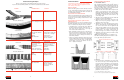
Worn sheave grooves are one of the principal causes of
premature belt failure. Get your money’s worth from a
new set of belts by inspecting the sheaves carefully!
• Clean dirty, dusty, or rusty sheaves. They will impair
the drive’s efficiency and wear out the belt cover.
Feel sheave grooves (wear gloves or use a rag) for
nicks or burrs, and file them smooth.
• Belts should ride in sheave grooves so that the top of
the belt is just above the highest point of the sheave.
If the grooves are worn to the point where the belt bot-
toms out (a clue: check for shiny groove bottoms), the
belts will slip and burn.
• If the groove walls are “dished out,” the bottom corners
of the belt will quickly wear off and cause rapid failure.
Check groove wear by sight, touch, or with a Bando
sheave gauge. If grooves are “dished out” 1/32" or
more — replace the sheaves!
Sheave installation and removal
To install QD
®
sheaves:
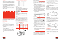
The conventional mounting position for QD
®
sheaves is
with the bushing flange located toward the bearing. The
reverse mounting position (for QD
®
bushing sizes JA
through J) is with the flange of the bushing toward the
open end of the shaft. For either position:
1. Make sure the sheave bore and the tapered cone
surface of the bushing are clean and free from
paint, dirt, and lubricants.
Do not use lubricants to
install QD
®
bushing assemblies.
Loosely assemble
the bushing in the sheave, and insert the cap
screws finger tight.
2. Slip the loosely assembled unit onto the shaft and
position it for proper belt alignment.
3. Tighten down the hollow head setscrews in the
flange on the key, snug enough to keep it in the
desired position on the shaft.
4. Tighten the cap screws alternately and progres-
sively to about half the recommended torque val-
ues in the table below. Check alignment and
sheave runout (wobble) and correct as necessary.
Continue to tighten the cap screws alternately and
progressively to the torque values below. To
increase leverage, use a wrench or length of pipe.
5. Tighten the setscrew on the key to hold it securely
in place during operation.
NOTE: Don’t allow the sheave to be drawn in con-
tact with the bushing flange. There should be a 1/8"
to 1/4" gap when properly mounted.
To remove:
1. Loosen and remove all mounting cap screws. Insert
two or three of the cap screws in the tapped removal
holes in the sheave. Start with the screw opposite the
bushing saw slot and progressively and alternately
tighten each screw until the cone grip is broken
between the sheave and the bushing.
2. Remove the sheave and bushing from the shaft. If the
bushing won’t slip off the shaft, wedge a screwdriver
blade in the saw slot to loosen.
QD
®
is a registered trademark of Emerson Electric.
Taper-Lock
®
and TL are registered trademarks of Reliance Electric.
QD Sheave Mounting Positions
Torque Values for Tightening QD Bushings
QD Bushing Wrench Torque QD Bushing Wrench Torque
(In. Lbs.) (In. Lbs.)
JA . . . . . . . . . . . . . .72 E . . . . . . . . . . . . . . .720
SH . . . . . . . . . . . . .108 F . . . . . . . . . . . . . . . .900
SDS . . . . . . . . . . .108 J . . . . . . . . . . . . . . .1620
SD . . . . . . . . . . . . .108 M . . . . . . . . . . . . . .2700
SK . . . . . . . . . . . . .180 N . . . . . . . . . . . . . .3600
SF . . . . . . . . . . . . .360 P . . . . . . . . . . . . . . .5400
“Dishing” of groove sidewalls shortens belt life
Belt should ride
like this
Low riding belts
indicate worn grooves
8
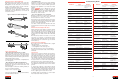
Troubleshooting Examples
Here are some examples of belt failures described on pages 6 and 7.
If you’ve encountered similar problems, check below for probable causes and solutions.
V-Belts
Problem Probable Cause Solution
Foreign object in drive Shield drive
Worn or damaged sheaves Replace sheaves
Sheave diameter too small Redesign drive
Back side idler diameter Replace with an inside idler
too small on slack side, or redesign
Slippage Retension drive
High temperature Remove heat source.
Improve ventilation
Broken belt
Excessive sidewall wear
Cracked bottom
Underdesigned drive Redesign drive
Crimp caused tensile Follow proper storage and
cord damage handling procedures
Belt was pried or forced Follow proper installation
on the drive guidelines
Foreign object in drive Shield drive
Belt ran onto pulley flange Align pulleys
Misalignment or non-rigid Align drive and/or
centers reinforce mounting
Bent flange Straighten flange
High temperatures Remove heat source.
Improve ventilation.
Check for special belt
construction
Broken belt
Excessive sidewall wear
Cracks in belt backing
Timing Belts