BEOLINK Master Link Handbook
MASTER LINK
MASTER LINK PREFACE This handbook deals with Bang & Olufsen’s BeoLink (Master Link), paying special attention to the installation requirements applying to it. Consequently, this handbook is especially targeted on dealers and installers. Any product, for example a stereo system, a PC, a natural gas system, etc., that has to be incorporated into a network needs to have certain requirements satisfied by the surroundings in connection with its installation.
MASTER LINK CONTENTS 1 READING INSTRUCTIONS How should I read this handbook 2 GENERAL DESCRIPTION What is a BeoLink system/Master Link system, and what can it do for me? 4 PRODUCT DESCRIPTION Description of BeoLab 3500, BeoLab 2000 and BeoLink boxes 11 SETUPS Description of recommended Master Link setups, compatibility setups, special setups and option programming 22 DIMENSIONING Description of how much cable may be used 23 INSTALLATION TYPES Description of various installation types 26 INSTAL
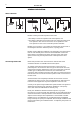
MASTER LINK 1 READING INSTRUCTION This handbook employs various symbols to illustrate audio products, video products and speakers. Unless otherwise specified in the text, these symbols merely have to be understood as covering one of these product areas and not as the specific product which the illustration may depict.
2 MASTER LINK GENERAL DESCRIPTION What is BeoLink? BeoLink is a Bang & Olufsen expression that covers: 1. The ability to create and operate audio-video systems, and 2. The ability to distribute sound and picture from a Bang & Olufsen main room system to other rooms in the home, and to operate the main room system from the rooms connected by means of BeoLink. BeoLink is not a product - it is a number of features that are the result of the intelligent interaction between products, a synergy effect.
MASTER LINK 3 BeoLink distribution covers the ability to distribute both audio and video signals. In the Master Link system audio and control signals are distributed by means of one single cable, whereas the distribution of video signals requires a coaxial cable network. Only BeoLink compatible products can be fully integrated in a BeoLink system, but previous system products may be integrated to a limited extent, as described in the chapter on Compatibility setups, page 17.
4 MASTER LINK PRODUCT DESCRIPTION Below you will find a description of the individual elements included with the Master Link products as well as their scope of application. Content BeoLab 3500 The BeoLab 3500 is an integrated link room speaker consisting of an active speaker with Master Link (ML) connection, an IR receiver and a display. BeoLab 3500 also has Master Control Link (MCL) connection. Furthermore, the BeoLab 3500 has a built-in clock.
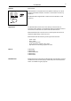
MASTER LINK Content 5 BeoLab 2000 BeoLab 2000 is an integrated link room speaker consisting of an active speaker with Master Link (ML) connection, an IR receiver and close-up operation. The BeoLab 2000 is supplied with a mains lead and a bracket for wall mounting. BANG & OLUFSEN 3m Application The BeoLab 2000 is used in link rooms where you wish to have an integrated active speaker. From the BeoLab 2000 it is possible to listen to all sources from the main room, both audio and video sources.
6 Content MASTER LINK BeoLink Active BeoLink Active consists of a control box, an IR receiver, a receiver cable and a mains lead. Application BeoLink Active speakers are used in link rooms where active speakers are required. All Bang & Olufsen active speakers may be connected. BeoLink Active has built-in sound control, meaning that tone and volume can be adjusted independently of the main room. With the tone control it is possible to adjust balance, bass, treble and loudness individually.
MASTER LINK Content 7 BeoLink Passive BeoLink Passive consists of a control box, an IR receiver, a receiver cable and a mains lead. Application BeoLink Passive speakers are used in link rooms where passive speakers are required. All Bang & Olufsen passive speakers may be connected. BeoLink Passive has built-in sound control, meaning that tone and volume can be adjusted independently of the main room. With the tone control it is possible to adjust balance, bass, treble and loudness individually.
8 Content MASTER LINK BeoLink Video BeoLink Video consists of a control box, a mains lead and a datalink cable. Apart from this you need an coaxial cable from the HF outlet of the video system in the main room. This cable is connected to the aerial input of the link room TV. Application BeoLink Video is used in link rooms where both sound and picture are required via a Bang & Olufsen TV set. With BeoLink Video it is possible to use all the sources in the main room.
MASTER LINK Content BeoLink Converter BeoLink Converter consists of a control box and a mains lead. 1.5 m Application BeoLink Converter is used when audio and video products with Master Link and Audio Aux Link (datalink) have to be interconnected. BeoLink Converter can be used in conjunction with both a video and an audio master. BeoLink Converter features autoconfiguration, meaning that it is able to detect automatically whether it is installed in a Master Link audio or in a Master Link video system.
10 MASTER LINK Content ML/MCL Converter ML/MCL Converter consists of a control box and an amplifier. 1.5 m Application ML/MCL Converter is used where a conversion from Master Link (ML) to Master Control Link (MCL) is wanted. Such a conversion is required if you want to maintain the existing Master Control Link system although the audio system in the main room is replaced with a Master Link driver, for example a BeoSound Ouverture.
MASTER LINK 11 SETUPS Recommended setups An object consisting of several parts can usually only be assembled in one way if the intended result is to be achieved. For example, a gearbox for a car will not perform optimally according to the specifications if you omit installing some of the gearwheels. If you manage to install one gearwheel too many, that will most likely cause trouble as well.
12 MASTER LINK For the Beolink 1000 terminal the key sequence is the following: Beovision: “digit” Beomaster/BeoSound: “digit” Link room products: “digit” The digit sequence to be used depends on the setup.
13 MASTER LINK Recommended main room setups Audio system in one room Option programming BeoSound Factory setting BeoSound : Ready for use : Option 1 Video system in one room Option programming BeoVision Factory setting BeoVision : Ready for use : Option 1 AV system in one room 1. Option programming BeoVision Factory setting BeoVision : Ready for use : Option 1 Option programming BeoSound Factory setting BeoSound : Ready for use : Option 1 2.
14 MASTER LINK Recommended setups for one product in the link room BeoLab 3500 Option programming Factory setting : Ready for use : Option 6 BeoLab 2000 Option programming Factory setting : Ready for use : Option 6 BeoVision MX 4002 Master Link Option programming Factory setting : Ready for use : Option 6 Coaxial BeoLink Active Option programming Factory setting Master Link : Ready for use : Option 6 BeoLink Passive Option programming Factory setting : Ready for use : Option 6
15 MASTER LINK BeoVision Avant Master Link Option programming BeoVision Factory setting BeoVision : Option 6 : Option 1 Coaxial BeoSound Ouverture Master Link Option programming BeoSound Factory setting BeoSound : Option 6 : Option 1 BeoLink Video Master Link BeoLink Video Datalink Option programming BeoVision Factory setting BeoVision Coaxial NOTE! Option and setups for a BeoVision connected to BeoLink Video, see Bang & Olufsen's Product Configuration Guide.
16 MASTER LINK Recommended setups for one Audio and one Video product in the link room Master Link Coaxial Master Link Audio* Video** *NOTE! Valid for all Audio link room products. **NOTE! Valid for Video link room products incl. BeoLink Video. Master Link Master Link Coaxial 1.
17 MASTER LINK Recommended compatibility setups Master Link Master Link BeoLink Converter Compatibility between products with Master Link connection and Audio Aux Link (datalink) connection or Master Control Link connection. One room setup 1. Option programming BeoVision Factory setting BeoVision : Option 2 : Option 1 Option programming Beomaster Factory setting Beomaster : Option 0 : Option 1 2.
18 MASTER LINK Two room setup 1. Option programming BeoVision Factory setting BeoVision : Option 2 : Option 1 Option programming BeoSound Factory setting BeoSound : Option 2 : Option 1 2. Option programming BeoVision Factory setting BeoVision : Option 2 : Option 1 Option programming Beomaster Factory setting Beomaster : Option 2 : Option 1 NOTE! Information as to which Beomasters and BeoVisions can be connected to BeoLink Converter, see Bang & Olufsen's Product Configuration Guide.
19 MASTER LINK Setups with ML / MCL Converter This product is used where the customer wishes to maintain his current MCL system and to replace the audio system in the main room with a Master Link driver. The ML/MCL Converter can be connected to all recommended MCL link room setups, see the Master Control Link Handbook. MCL Master Link BeoLink Video Datalink 1. Option programming BeoSound Factory setting BeoSound : Ready for use : Option 1 2.
20 MASTER LINK Special setups Further to the recommended setups, there are two additional combinations. The reason why they are not mentioned under recommended setups is that they do not fully live up to Bang & Olufsen’s own standards as regards operating simplicity. They have been included anyway, because in some situations they might be appropriate, and they will always permit operation of the basic functions such as source selection (radio, CD, a.tape, etc.
MASTER LINK 21 Moreover, option 4 can be used if the link room and the main room are located in such a way that both rooms will be operated simultaneously. By setting the link room to option 4, the room can be operated independently of the main room, because the link room will only accept information from the terminal if the LINK key has been actuated.
22 MASTER LINK DIMENSIONING Max. 400m ML Cable It is possible to interconnect 16 Master Link products, including the main room products, in one system, and a maximum of 400 m of Master Link cable may be used. The cable between the receiver and BeoLink Active/Passive may not exceed 5 m. 5 m is included from the factory. A special 15 m low capacity receiver cable can be ordered, part no. 6270668.
MASTER LINK 23 INSTALLATION TYPES The following section gives a brief introduction to two typical installation types, namely the visible and the invisible installation. The examples include various applications of Bang & Olufsen’s installation accessories, which are shown at the end of the handbook. The illustrations give only a few installation examples. There are many alternatives, of course.
24 MASTER LINK Another type of invisible installation is shown below. This installation can be made for example in apartments with no access to the attic or basement. In this example the following has been used: 1. 2. 3. 4. 5. 4 x Master Link cable with two plugs Master Link cable without plugs 4 x Master Link wall socket 1 x datalink cable (included with BeoLink Video) 1 x BeoLink Video Aerial installation Aerial installation with built-in splitter. Aerial installation with external splitter.
MASTER LINK Build-in kit for IR-eye 25 The build-in kit for IR-eye is used for invisible installations. There are two different build-in kits. One for solid walls (part no. 3375187), which contains a fixture box, a spacer piece, a plastic cover (to close the box under construction) and an ornamental ring. The other kit is for light partition walls (part no. 3375188) and contains two brackets and an ornamental ring.
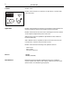
26 MASTER LINK INSTALLATION TIPS Placing of receiver The receiver must be placed so that nothing prevents it from receiving the signals from a Bang & Olufsen remote control. When deciding on the position of the receiver, remember that it should not be possible to activate more than one receiver at a time using a remote control terminal. The diagram shows that receiver 3 is placed appropriately, whereas receiver 1 can be activated from room 2. Receiver 1 should be placed as receiver 2 instead.
MASTER LINK 27 Use of Master Link junction box: 1. Length-adjustment of cable, e.g. from 10 m to 8.5 m. 2. Colour-change of cable. For aesthetical reasons all ML cables with plugs are available in the colour black only. When making visible installations it may be necessary to use a grey cable which can easily be connected via the junction box. 3. Connections between products. Max. 4 ML cables in one junction box.
28 MASTER LINK Central placing of BeoLink boxes BeoLink Passive BeoLink Active Cupboard or basement or attic BeoLink Video As appears from the illustration, BeoLink boxes can be placed in a central location. (However, maximum cable lengths may not be exceeded, and the same applies to maximum and minimum ambient temperatures. See the sections 'Dimensioning', page 22, and 'Placing of control box', page 26, for further information).
29 MASTER LINK TECHNICAL DESCRIPTION The following section contains a brief description of the cabling most often used in connection with a BeoLink installation. Pictures (satellite, video tape recorder and ordinary TV broadcasts) are distributed through a 75 ohm coaxial cable. Regarding part nos., see 'Accessories', page 39. Master Link cable Pin no.
30 MASTER LINK Power Link cable without wire for display data pin 2 pin 3 pin 4 pin 5 17 15 13 shield = brown = yellow = green = ground signal, left channel loudspeaker on signal, right channel 21-pin A/V cable with RGB connection: 21 19 = = = = 20 18 16 14 12 11 10 9 8 7 6 5 4 3 2 1 1 2 3 6 4 15 13 11 9 7 5 16 18 20 17 19 8 21 10 12 14 2 1 6 3 4 15 13 11 9 7 5 16 17 19 18 20 8 21 10 12 14 pin 1 = pin 2 = pin 3 = pin 4 = pin 5 = pin 6 = pin 7 = pin 8 = pin 9 = pin 10 = pin 11 = pin 12 = p
31 MASTER LINK Receiver cable 1 2 3 4 5 1 2 3 4 5 = = = = = Yellow Grey Green White Brown NOTE! Disconnect your entire Bang & Olufsen system from the mains while you make the connections!
32 MASTER LINK TROUBLESHOOTING GUIDE Master Link products, e.g. BeoLab 3500 When carrying out troubleshooting on a Master Link installation, the first thing to do is to apply the method of exclusion. First disconnect the main room and the link room, one at a time, to ascertain whether the fault is in the main room or in the link room. Then disconnect the individual products, one at a time, until the faulty product or the faulty connection has been found.
MASTER LINK Trouble No sound and no operation 33 Possible cause The product is connected to the mains and the stand-by diode is on. If the above is OK, do as follows: - Meter data+ (pin 2) relative to ground Meter data- (pin 1) relative to ground Where no transmission, +/- 200 to 300 mV should be metered. When data is being transmitted, 0V should be metered. Measurement with oscilloscope. Meter the following: No transmission ———————————— + 0.25 ———————————— 0 ———————————— -0.
34 Service mode MASTER LINK Products with a display feature a service mode in which Master Link faults can be displayed. Please note that the error reading indicates that the fault is a system fault, which does not mean that the fault is in the particular product that is displaying it. Beolab 3500 and BeoVision Avant are examples of products providing the service mode feature. Check the service manual for the individual products to see how these procedures are accessed.
MASTER LINK 35 GLOSSARY Audio Aux Link Perhaps better known as AV connection . Connection between the audio and video systems. The connection is established through a 7-pin datalink cable. 21-pin AV cable / SCART Standard connection between a TV set and a video tape recorder. The cable is specified for transferring RGB signals. AV system Audio/video system. Integration of audio and video, permitting sound to be transferred from one system to the other.
36 MASTER LINK Master Control Link (MCL) Master Control Link is the name of the former connection between main room and link room. Master Link (ML) Bang & Olufsen’s new systems interface. Master Link is the connection between the products in the main room and those in the link room but it is also the connection between the audio system and the video system. Master Link driver BeoSound and BeoVision with Master Link socket. One of these products is always required in a Master Link setup.
MASTER LINK Notes : 37
38 MASTER LINK
39 MASTER LINK ACCESSORIES For information about other spare parts, see the "Accessories" handbook. Used for connection between two products or between a wall socket and a product. Ø 6.5 mm 6270632 3.0 m with one plug, black 6270708 6270709 6270631 6270711 6270633 6270635 0.5 m with two plugs, black 1.5 m with two plugs, black 3.0 m with two plugs, black 5.0 m with two plugs, black 10.0 m with two plugs, black 20.0 m with two plugs, black Running metres of Master Link cable.
40 MASTER LINK Used for connection between BeoLink Converter and one Audio and one Video product with Datalink connections. AUX T-branch 6270702 Used for serial connection of active speakers. 6270706 6270705 Power Link T-branch 0.3 m 1.6 m Used for connection between two products or between a wall socket and a product. Datalink cable Black Grey Length 6270222 6270393 1.5 m, two plugs 6270639 6270640 3.0 m, two plugs 6270353 6270394 5.0 m, two plugs 6270337 6270395 10.
41 MASTER LINK 7220026 7211072 Male, metal Female, metal Length: 2.5 m Colour: white Internal dimensions: 8 x 18 mm Available in cartons of 10 pieces each. 2560257 2548255 2548256 2548257 7219071 2369117 Coaxial plug Cable cover, narrow Outside corner (1) Inside corner (2) L-shaped piece (3) Junction box (incl. special terminal strip f. MCL) (4) Nail plugs (100 pieces) for mounting of Cable covers. For concealing wiring from BeoLab 3500 on the wall. Length: 2.
42 MASTER LINK Wall socket with 8-pin DIN socket with solder terminals. Used for plug connection between audio system and wall socket. 7210675 7210473 7210512 Wall socket, 8-pin DIN 49 x 49 x 24 mm, white (DK) 49 x 49 x 24 mm, grey (DK) 80 x 80 x 24 mm, white (EURO) DK fixture box for wall socket. Used for flush mounting in brick or plasterboard walls. Fixture box Dimensions: 80 x 83 mm 7219089 DK mounting base for wall socket. Used for mounting on the outside of e.g. a brick wall.
43 MASTER LINK Plate for covering installations not in use. 3164593 3164707 Blanking plate 49 x 49 x 24 mm, grey (DK) 49 x 49 x 24 mm, white (DK) Outdoor mounting box for ML and MCL transceiver. Outdoor mounting box Dimensions: 75 x 125 x 175 mm 3132221 Used for invisible installations in solid walls. Build-in kit for ML transceiver, solid wall 3375187 Used for invisible installations in light partition walls.
44 MASTER LINK Used for length-adjustment of ML cable, colour-change of cable and for connections between products. 3132170 3132197 3132220 black grey white Used for Master Link connections between products. 3375189 3629132 ML junction box, large black Professional tools for terminating. 3629127 ML junction box, small For terminating in ML wall socket For terminating in ML junction box.
MASTER LINK Notes : 45
46 Notes : MASTER LINK
MASTER LINK
TELEPHONE 96841122* CABLE ADDRESS BANGOLUF TELEFAX 97853911 3540230 04-97 B PRINTED IN DENMARK BY BOGTRYKKERGÅRDEN AS, STRUER BANG & OLUFSEN DK - 7600 STRUER DENMARK