Owner’sManual with Installation Instructions Banks PowerPack System ® Including Stinger®-Plus, Stinger® and Git-Kit® ® with AutoMind Programmer 1999-2003 Ford Power Stroke 7.3L Turbo-Diesel F250/F350 Trucks and Excursions Gale Banks Engineering 546 Duggan Avenue • Azusa, CA 91702 (626) 969-9600 • Fax (626) 334-1743 Product Information & Sales: (888) 635-4565 Customer Support: (888) 839-5600 Installation Support: (888) 839-2700 bankspower.com ©2014 Gale Banks Engineering 02/24/14 PN 96336 v.11.
Product available from Banks Power for 1999-2003 Ford 7.3L Banks Power Elbow (P/N 48651-48652, 48661-48663) - Reduces stock outlet and pipe backpressure Banks Monster® Exhaust System Sport (P/N 48789) Single and Dual (P/N 48653-48660, 47391-47399) - Increases exhaust flow, cuts backpressure, lowers exhaust gas temperatures (EGTs) and increases power.
Banks Git-Kit Systems (P/N 47401, 47511-47514) Contains: - Monster Exhaust - AutoMind Programmer Banks Stinger Systems Contains: - Ram-Air IntakeFilter - Monster Exhaust - AutoMind Programmer - Big Head Wastegate Actuator Banks PowerPack Systems Contains: - Ram-Air Intake Filter - Monster Exhaust - Quick-Turbo - TransCommand - Techni-Cooler System - Big Head Wastegate Actuator - AutoMind Programmer Banks Six-Gun Bundle (P/N 46594-46613) Contains: - Ram-Air Intake Filter - Monster Exhaust - Six-Gun Tuner -
General Installation Proctices 7. During installation, keep the work Dear Customer, If you have any questions concerning the installation of your Banks Power System, please call our Technical Service Hotline at (888) 839-2700 between 7:00 am and 4:00 pm (PT). If you have any questions relating to shipping or billing, please contact our Customer Service Department at (888) 839-5600. Thank you. 1.
Section 1 LEGAL & WARRANTY INFORMATION Banks AutoMind Programmer Disclaimer of Liability and Limited Warranty THIS IS A HIGH PERFORMANCE PRODUCT. USE AT YOUR OWN RISK. Please read these terms and conditions (the “Agreement”) carefully prior to installing and/or using any BANKS Product (the “Product”). By installing and/or using the Product you agree to be bound by the following terms and conditions.
Section 2 END USER LICENSE AGREEMENT (EULA) IMPORTANT-READ CAREFULLY: This End-User License Agreement (“EULA”) is a legal agreement between you (either an individual or a single entity) later referred to as “LICENSEE” and Gale Banks Engineering (hereinafter referred to as “Company” for the software product related to Banks iQ and Banks Automind Programmer later referred to as “SOFTWARE”. By installing, copying, or otherwise using the SOFTWARE, you agree to be bound by the terms of this EULA.
Section 3 MONSTER® EXHAUST INSTALLATION (PART 1 OF 2) NOTE: This Manual contains installation instructions for Monster Exhaust, Techni-Cooler, Quick-Turbo and AutoMind Programmer. Depending on the system you have purchased, some of these components may not be included. Review the entire manual and select the installation sections that apply to your product. For Git-Kit installation, proceed to Step 2. loose, as we have found several vehicles with exhaust leaks in this area.
Section 4 TURBOCHARGER REMOVAL For Stinger installation, proceed to Section 5, Step 4. 4. Disengage the exhaust-backpressure CAUTION: Anytime the turbocharger is removed from the engine, take care that no foreign objects enter any of the turbocharger connections on the engine or the turbocharger.
Section 5 QUICK-TURBO® AND COMPRESSOR WHEEL INSTALLATION For vehicles with build dates in 1998, proceed to Step 4. 1. Remove the five bolts around the outside of the compressor cover and carefully remove the cover by pulling it straight off the turbocharger assembly, avoiding contact with the compressor wheel. Use caution to avoid damaging the sealing o-ring around the outside diameter of the compressor back plate. 2. Secure the turbine wheel in a vise by clamping the hub of the turbine wheel.
Section 6 MONSTER® EXHAUST INSTALLATION (PART 2 OF 2) 1. For 2002-03 models only, it is necessary to relocate the factoryinstalled frame-mounted hanger pin that is located behind the transmission crossmember. A. Remove the two (2) nuts that hold the frame-mounted hanger pin to the frame rail, save for reinstallation later. Remove the frame-mounted hanger pin from vehicle. B. Remove the two (2) 8mm studs from the frame-mount hanger pin.
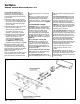
Figure 4- Intermediate-Pipe Cut For Excursions, install a 4” clamp onto the muffler outlet. For all applications, Install the Front Monster tailpipe over the rear axle housing and into the outlet of the Monster muffler. Loosely tighten the clamp on the muffler outlet to secure the Front tailpipe. Insert a 4” clamp into the outlet of the Front tailpipe. Install the Rear tailpipe inlet into the Front tailpipe outlet. Install the rear tailpipe hanger into the corresponding rubber hanger on the vehicle.
Figure 5 (see pages 24-25 for parts identification) 12 96336 v.11.
96336 v.11.
Section 7 BANKS TECHNI-COOLER® INSTALLATION For Git-Kit installation, proceed to Section 9. For Stinger installation, proceed to Section 8. For Stinger-Plus installation, proceed to Step 23. For PowerPack installation, continue with Step 1. 1. Remove the factory intercooler plumbing from the vehicle. Loosen the clamps on the boost tubes and remove the boost tubes. (It is assumed that the compressor discharge plenum casting has been removed from the vehicle at this point.) 2.
side of the clamp. Reinstall the bracket using a #56 hose clamp provided to secure the filter/dryer unit to the bracket. NOTE: Before slipping any boost tubes and the corresponding hoses, into position, ensure that all connection ends are clean and free of any oil residue and contaminates. Clean compressor outlet and all connection points with a non-oil based solvent such as Acetone, Mineral Spirits, Denatured Alcohol or Lacquer Thinner. Read and follow the manufactures operation instruction 15.
Section 8 DYNAFACT® INSTRUMENTATION INSTALLATION 1. If gauges are being installed into an existing gauge panel, this step may be skipped. If gauges and a gauge panel or console are being installed, choose a location where the driver can easily view the gauges. This will typically be to the right of the accelerator pedal, under the lower edge of the dash panel. Mount the gauge panel with the machine screws, washers, and nuts provided. 2.
9. Install one 1⁄8” NPT female by 1⁄ 8” compression 90° fitting onto the threaded end of the tee. Sparingly apply pipe sealant tape or paste on the male pipe threads, and adjust the 90° fitting to point back toward the firewall, as shown in Figure 7. Do not allow any sealant to cover the small hole in the fitting. Do not over-tighten the plastic fitting. Figure 8- Gauge Connections 10.
Section 9 PREPARING VEHICLE & CONNECTING BANKS AUTOMIND® PROGRAMMER Follow the vehicle preparation steps to ensure a complete program installation. These steps must be performed prior to installing the Banks AutoMind calibration. Familiarize yourself with Banks AutoMind Programmer keypad controls. The keypad will allow the user to navigate between screens and to select functions. (See Figure 9). WARNING 1.
Section 10 INSTALLING BANKS AUTOMIND® CALIBRATION PROGRAM WARNING: Do not unplug the Banks AutoMind Programmer while uploading or downloading a program. Doing so can damage the vehicles ECM. –IMPORTANT- When the AutoMind programmer is plugged into the vehicle OBDII port connection, follow the on screen instruction and turn the ignition key ‘ON/OFF’ when prompted by the programmer, but do not start the engine. Apply the parking brake to turn off lights and conserve the battery.
Section 11 RESTORING FACTORY TUNE The stock calibration can be reinstalled at any time by following the instructions below. This feature will remove the Banks AutoMind calibration and will return the vehicle to its stock condition. The Banks AutoMind calibration will be saved in the Banks AutoMind programmer. Figure 14 7. The data transfer may take a few minutes to complete. Once the upload is complete you will be instructed to “Turn Ignition Switch OFF and Remove Key, Press OK to continue.
Section 13 DATA LOGGING The Data Acquisition feature allows you to view various sensors that are monitored through your vehicle’s ECM, and record data during acceleration runs. 1. Plug in your Banks AutoMind Programmer and turn the key to the ON position. Do not start the vehicle. 2. After the welcome screen, scroll up or down in the main menu screen and highlight to select ‘ADDITIONAL FEATURES’ and press the ‘OK’ button. 3.
Section 15 TROUBLESHOOTING BANKS AUTOMIND® PROGRAMMER Most issues can be resolved by ensuring that the AutoMind Programmer is up-to-date. Visit www.bankspower.com/downloads to download the AutoMind Programmer Update Utility on your Computer, then use the update utility to ensure that the AutoMind Programmer has the latest files available.
Section 17 SERVICE TIPS 1. If the need should arise for you to have your vehicle serviced, the Banks AutoMind Flash Program should be removed from the vehicle. 2. It is not uncommon for a service provider to update the program in the vehicle ECU. If this occurs, the AutoMind Flash tune will be lost. 3. Your system includes two Banks Power logos that have been designed to compliment the Ford badging on your truck.
List of Components Item # Part # Description 1 25505 TECHNI-COOLER INTERCOOLER Git-Kit Stinger Stinger-Plus PowerPack -- -- -- 1 2 41301 ELBOW, Compressor Outlet (1999 model only) -- -- -- 1 3 41305 TUBE, Intercooler Inlet -- -- -- 1 4 41309 TUBE, Intercooler Outlet -- -- -- 1 5* 41313 TWINRAM, Intake Assembly, (1999 model only) -- -- -- 1 24440 WHEEL, Compressor, (1999 ⁄ 2 –2001 models only) 6 1 24455-01 HOUSING, Turbine -- -- 1 1 -- -- 1 1 7* 53520
Item # Part # Description Git-Kit Stinger Stinger-Plus PowerPack 40 41360 41 26096 SPACER, ⁄ 8” x ⁄ 8” -- -- -- 2 SPACER, 5⁄ 8” x 3⁄ 8” -- 2 2 2 42 91253 BOLT, ⁄ 16”-24 x 1” Hex -- -- -- 1 43 91144 BOLT, ⁄ 4”-28 x 2” Hex -- -- -- 4 44 91140 BOLT, ⁄ 4”-28 x 1” Hex -- -- -- 10 45 91119 BOLT, 1⁄ 4”-20 x 1 1⁄ 4” Hex -- -- -- 1 46 91789 BOLT, 8mm 1.25 x 30mm Hex -- -- -- 2 47 91792 BOLT, 8mm 1.
Notes 26 96336 v.11.
Notes 96336 v.11.
Gale Banks Engineering 546 Duggan Avenue • Azusa, CA 91702 (626) 969-9600 • Fax (626) 334-1743 Product Information & Sales: (888) 635-4565 Customer Support: (888) 839-5600 Installation Support: (888) 839-2700 bankspower.