
Owners manual


96444 v.3.0 7
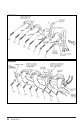
TorqueTubes. Instructions are provided,
however, to allow for reinstallation should
you decide to do so. The tabs that attach
the spark plug boot heatshields must be
bent to line up with the bolt holes in the
manifold flange. Adjust the tabs as required
so spark plugs may be serviced. End tabs
on some heat shields may not line up with
bolt holes. In this case use center mounting
tabs only.
B. Spacers are used with some bolts to
mount the ignition coil bracket, emissions
control bracket and heat shield. Bend
the mounting tabs for these components
to line the tabs up with the manifold
and spacer bolt holes. The dipstick may
be bent slightly as needed to clear the
manifold tube. Be careful not to kink the
dipstick tube.
C. Because of the tight confines, we
suggest that the EGR tube and air injection
tube (if equipped) be tightened into
the manifold with the manifold loosely
attached to the head (this allows for some
additional freedom of movement). In some
cases, the EGR and air injection tubes may
have to be tightened with the manifold
completely separated from the head,
then bolted to the head when wrenching
the tubes is completed. Air injection
tube may be loosened from its upper
support bracket to aid in alignment during
installation. A dab of anti-seize on the tube
threads will aid in assembly.
Once this procedure is complete, install
remaining manifold bolts with anti-seize
applied.
14.
Reconnect the EGR valve exhaust feed
tube and air injection tube to the bungs
on the left-hand PowerPack
® exhaust
manifold. Feed tubes may be bent slightly
if needed. A light lubricant or Anti-Seize on
the threads eases installation.
IMPORTANT! Some motorhomes may
have the transmission shifter cable
and in some cases the speedometer
cable routed near the left (driver’s)
side TorqueTube manifold, exposing
them to heat. This routing will
vary depending on the coach
manufacturer, but it is important to
protect these cables from heat in any
case.
Wrap one piece of the 3 x 16” foil heat
shield blanket around the shifter cable
where the cable crosses from the
transmission to the frame rail in the
proximity of the exhaust manifold. Secure
the heat shield in place with the wire
ties provided. Cut the remaining wire off,
making sure that the sharp wire ends will
not chaff the cable in any way.
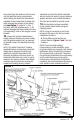
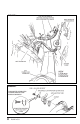
If the speedometer cable is also routed
near the exhaust manifold, wrap it with the
second piece of foil heat shield blanket,
securing it with the wire ties provided. See
Figure 6.
15.
Reconnect air injection tube (if used)
to two-bolt flange at rear of right exhaust-
manifold head flange. (Only manifolds for air
injected engines will have this flange.)
Use new gasket, provided, two
5
⁄
16
–24 x
5
⁄
8
hex bolts, and four
5
⁄
16
” circle-lock washers.
Washers are used in pairs on each bolt, the
ramps on the surface of each washer must
face each other when installed on bolt. See
Figure 7 for proper washer installation.
16.
Check that the positive battery cable
to the starter motor has at least three
inches of clearance to any part of the
exhaust manifold tubing. Also check that
the cable will not rub on any sharp edges
that could cut through the insulation and
cause a short. Reposition or tie the cable in
place to correct any of these conditions.
17.
Install spark plugs and reconnect plug
wires.
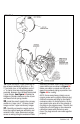
18.
Install the starter heatshield by first
slipping the No. 56 hose clamp through the
slots in the heatshield as shown in Figure
8. Now, with the heatshield between the
TorqueTube exhaust manifold and the
starter, feed the tail of the No. 56 hose
clamp between the solenoid and starter
motor, then tighten.