
emissions kit Owner manual


3
Push one end of the blue silicone vacuum
hose through the drilled hole in the side of
is inside the pressure chamber. Once this hose is
inside the pressure chamber and pull it through.
run a bead of silicone sealant around the
inside of the pressure
chamber.
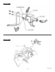
Temporarily install the pressure chamber
on the intake manifold. Make sure the base
gasket and new EGR hold-down studs (supplied
with the Banks Sidewinder turbo system) are in
place. Check that the pressure chamber sits
squarely against the gasket and will contact it
before tightening it down. Do not use any spacers or
washers between the EGR studs and the mounting
ears of the EGR valve. See Figure 5.
Lift the pressure chamber from the intake
manifold and push the inner half of the blue
silicone hose over the nipple on top of the EGR valve.
Remove any hose clamps or spring clips that may
have previously been used on the hose-to-nipple
connection. See Figure 5.
5
” I.D. x
4
”
5
IMPORTANT
Two different types of EGR control are found on the
Pulse Width Modulated. The type of system used
can be identified by observing the cluster of factory
installed solenoid valves above the rear of the left
system identification. Once your system type has
-
ceed to the final step for the electrical hook-up.
NOTE: The EPR (heat riser valve) must be in place for
the system to operate properly. Make sure you have
the proper Banks exhaust cross-over pipe that will
allow the EPR valve to mount in place on the driver’s
side exhaust manifold outlet. The vacuum line to the
EPR must be attached to the EPR valve and the EPR
solenoid.
VACUUM SWITCHED EGR SYSTEM
Vacuum Switched EGR systems can be identified by
the presence of two solenoid valves over the rear
used the Pulse Width Modulated EGR system; pro-
ceed directly to the instructions covering the Pulse
Width Modulated EGR system.)
VACUUM SWITCHED EGR PLUMBING
Route and connect the hoses as shown in Figure 7.
Use the black spring band clamp to secure the blue
silicone hose. Use the green clamps on the neo-
prene hose. The neoprene hose supplied need not
be used if the existing neoprene vacuum line on the
vehicle is long enough and in good condition. When
Figure 9.
PULSE WIDTH MODULATED EGR
Pulse Width Modulated EGR systems can be identi-
fied by the presence of three solenoid valves over
it uses the Vacuum Switched EGR system; go back
to the section covering the Vacuum Switched EGR
plumbing.)
PULSE WIDTH MODULATED EGR PLUMBING
Route and connect the hoses as shown in Figure 8.
Use the black spring band clamp to secure the blue
silicone hose. Use the green clamps on the neoprene
hose. The neoprene hose supplied vehicle is long
enough and in good condition. When the vacuum
Figure 10.
6.
8.
7.
9.
10.