owners manual with installation instructions stinger ® s y s t e m chevrolet/GMC 6.5L diesel PICKUPS AND SUBURBANS with factory turbo option 1993-EARLY 1994 NON-CATALYTIC CONVERTER 1994-LATER with catalytic converter THIS MANUAL IS FOR USE WITH systemS gale banks engineering 546 duggan avenue • azusa, ca 91702 (626) 969-9600 • fax (626) 334-1743 www.bankspower.com ©2009 gale banks engineering 02/12/09 p.n. 96309 v.3.
General Installation Practices For ease of installation of your Banks Stinger™ System, please read this 16- page owner’s manual before starting any work. Become thoroughly familiar with all components and phases of the installation before starting any work. other damage. Route or tie away from critical areas as required. Keep all wires a minimum of 6” from hot exhaust parts, 8” or more is recommended whenever possible. 1.
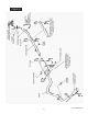
FIGURE 1 Remove the decorative cover from the top letter “R” drill (.339 dia.), then tap the hole with a ⁄ “ NPT tap. Clean all chips from inside the casting. 6. of the engine. Unbolt and remove the air 1 inlet casting from the top of the intake manifold. Cover the intake manifold opening to prevent foreign objects from falling into the engine. warning! Any foreign object that falls into the intake manifold can cause serious engine and/or turbocharger damage upon engine start up.
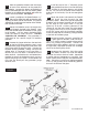
For 1993 and early 1994 applications, follow Steps 9-13.For 1994 and Later applications, skip to Step 14. through their rotation and check that binding does not occur. Correct as necessary. Note: Some resistance is always present from the wastegate actuator. Reinstall the turbocharger heatshield and the CDR valve. WASTEGATE MODIFICATION EXHAUST SYSTEM Unbolt and remove the heatshield from the Remove the factory exhaust system by first 9. turbocharger. On models with a support 14.
FIGURE 3 FIGURE 4 5 P.N. 96309 V.3.
FIGURE 5A 6 P.N. 96309 V.3.
FIGURE 5B - PICKUP TRUCK 7 P.N. 96309 V.3.
FIGURE 5C - SUBURBAN 8 P.N. 96309 V.3.
Extended Cab and Crew Cab models: The extension pipe will install between the turbine outlet pipe and the intermediate pipe. Temporarily place the intermediate pipe, muffler and tailpipe in place using the hangers and hanger clamps. Position the components such that the turbine outlet pipe and the intermediate pipe are in alignment with each other and the rubber hangers are swung slightly forward (see Figure 6).
Slide the protective sleeves over the longer Install one end of the 1⁄ ” diameter plastic 8 23. of each of the wire ends on the probe and 27. tube provided into the nut and ferrule fitting the leadwire. Connect the longer red leadwire to the red thermocouple wire and the shorter yellow leadwire to the yellow thermocouple wire with the screws and nuts provided. See figure 7. earlier installed in the intake plenum and tighten the nut.
OPERATING CHARACTERISTICS Your Banks Stinger will allow your GM 6.5L factory turbocharged engine to produce more power and respond quicker well within the safe operating range of the engine as long as the following guidelines are adhered to. If the vehicle approaches these EGT levels under these conditions, downshift the vehicle to reduce the load, or back off the throttle.
PUMP ADJUSTMENT PROCEDURE Using a syringe or similar means, remove as much diesel fuel as possible from the injector pump housing. This will make it easier to view the Allen-head adjustment screw through the slot in the bottom of the pump housing when it is rotated into position. NOTE: This section applies to 1993 and early 1994 model year vehicles only. NOTE: The engine must be COLD before starting this procedure. NOTE: Utmost cleanliness should be exercised.
at their highest ends, and fill them with clean diesel fuel using a small funnel. Reattach the hoses. bowl with clean diesel fuel. Hold the throttle in the idle position. With the bolts removed from the pump cover, position the cover about 1/ ” forward, toward the shaft end, and about 1/ ” above the pump. Guide the cover downward and rearward into position, being careful not to damage the cover seal. Reinstall the bolts with the flat washers against the pump cover. 4 Reconnect batteries.
Cleaning and Oiling the banks ram-air Filter Notification The Banks Ram-Air Filter comes pre-oiled and no oiling is necessary for initial installation. EXCESS HEAT WILL SHRINK THE COTTON FILTER MEDIA. COMPRESSED AIR WILL BLOW HOLES IN THE ELEMENT. AEROSOL OILING After cleaning air filter always reoil before using. Spray Banks Ram-Air filter oil down into each pleat with one pass per pleat. Wait 10 minutes and re-oil any white spots still showing. 6.
parts list Stinger System, GM 6.
Gale Banks Engineering 546 Duggan Avenue • Azusa, ca 91702 (626) 969-9600 • Fax (626) 334-1743 Product Information & Sales: (888) 635-4565 bankspower.