
User Manual


44 97055 v.8.0
Your Banks Brake CBC/SmartLock is
equipped with diagnostic features
that will detect and display certain
errors. If the Banks Brake does not
pass the FUNCTIONAL TESTING or
ceases to function properly, re-check
all the connections per the installation
instructions. Make sure that electrical
connections are tight and secure and
that the vacuum hoses are not kinked or
pinched.
If the Brake Enable Switch does not light
up within a few seconds, the following
diagnostic procedures can be carried out
to identify and correct the problem:
1. With key ON and the engine OFF,
turn the Brake Enable Switch ON. If
the Switch does not light up, check the
red power wire to the CBC/SmartLock
module, and it’s fuse.
2. If the Switch begins to flash an
error code, check the troubleshooting
table for their meaning.
The Switch will flash in a certain
sequence if a connection is incorrect
or if there is a problem with the
system – this sequence will identify
one or more diagnostic codes. A Banks
Brake diagnostic code is comprised
of 2 digits. Each code is expressed
in a sequence of 2 sets from the
flashing Switch separated by a brief
pause, followed by additional flashing.
A longer flashing of the Switch
separates the sequences. The Switch
will continue to flash to display all the
errors, and then repeat. Table 1 lists
the available diagnostic codes and
their recommended course of action
for each. For example, if a faulty OBD
II connection is detected (code “2,4”)
by the Banks Brake CBC/SmartLock,
the Brake Enable Switch will flash the
following sequence when the key is
on:
(1) Two times flashing
(2) One time quick flash
(3) Four times flashing
(4) One time longer flashing.
The flashing sequence will repeat
continuously. When the problem is
corrected, the diagnostic code will be
eliminated and replaced by a steady
light.
NOTE: If multiple codes are set, they
will be displayed in a series separated
by the longer flashing light. When
reading codes, make sure to watch
the entire series until you see the first
code repeat.
3. If the Enable Switch is lit solidly,
then inspect all the mechanical
components in the System. With the
engine cold and the hood up, have
someone start the engine. Make
sure the transmission is in park.
Watch the actuator arm on the Brake
housing. It should move forward
(closed). Whenever the accelerator
pedal is pressed, the Brake should
open (actuator arm should move back
towards the firewall).
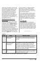
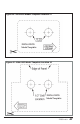
Checking the performance of the
vacuum pump:
WARNING: The Pump must never
be run open to the atmosphere,
as this will damage the Pump
diaphragm. The Pump must
always be connected to the
Vacuum Solenoid or it’s vacuum
nipple must be plugged. The
warranty on the Pump will be
voided if the Pump is allowed to
run open to the atmosphere.
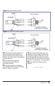
With the vehicle safely in park and the
engine off, disconnect the
5
⁄16” hose
from the Vacuum Solenoid (Port 1,
Figure 20 & 21). Connect this hose
to a vacuum gauge while keeping the
Section 10
Troubleshooting