
User Manual


1. Disconnect the negative (ground)
cable from the battery (if there is more
than one battery, disconnect both
negative cables). Secure the cable so
it cannot accidentally come in contact
with the post.
2. Raise the vehicle high enough to
remove the transmission and support
it securely with properly weight-rated
safety stands, ramps or a commercial
hoist. Take care to balance the vehicle
to prevent it from slipping or falling.
When using ramps, be sure the wheels
are centered squarely on the topsides.
Set the parking brake and securely
block the wheels that are on the
ground. CAUTION: DO NOT WORK
UNDER ANY VEHICLE SUPPORTED
ONLY BY A JACK. SEVERE INJURY
MAY RESULT.
3. Carefully remove the Banks Torque
Converter from the shipping container.
Be careful not to damage the shipping
container as it will be used to return
the factory torque converter to Gale
Banks Engineering.
4. To avoid pump seal damage during
converter installation, inspect the
Banks Torque Converter hub and
hub drive notches for sharp edges,
burrs, scratches or nicks. It may
be necessary to polish hub and/or
notches with 320/400 grit sandpaper
and crocus cloth.
5. If necessary, disconnect or remove
the lower exhaust components to
make room for transmission removal.
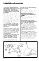
6. Remove the two engine-to-
transmission struts, if equipped (see
Figure 1).
7. If necessary, remove the starter
motor. Retain the hardware for
reassembly.
8. Remove the torque converter
access cover located on the underside
of the front of the transmission.
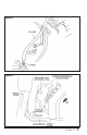
9. Remove the fill tube bracket
bolt and pull the tube out of the
transmission. Retain fill tube O-ring
and hardware for re-assembly (see
Figure 2). On 4x4 models, remove the
bolt attaching the transfer case vent
tube to the converter housing.
10. Remove the flywheel housing
plugs (see Figure 3). Insert the Dodge
Barring Tool (available from Banks, p.n.
97007) into the flywheel housing and
rotate the crankshaft in the clockwise
direction until the converter bolts are
accessible. Remove the converter
bolts and retain for re-assembly.
Installation Procedure
Figure 1
6 96730 v.7.0