
Manual
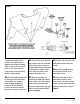


57. Remove the valve spring and
valve spring compressor tool from
the valve stem.
58. Carefully, release the
compression on the spring and
remove the spring from the tool.
59. Install a new exhaust valve
spring into the tool and compress the
spring using the same procedure
outlined in
Step 12.
60. Install the new valve spring over
the stem and ensure that the spring
is seated securely.
61. With the spring still compressed,
install the valve stem keepers
removed in
Step 14.
62. Carefully release the
compression on the spring by
rotating the tool handle counter
clockwise. Remove the compressor.
63. Verify that the valve stem
keepers are fully seated by tapping on
the valve stem with a plastic hammer.
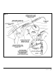
64. Reinstall the rocker stand
assembly ensuring that both pushrods
engage the rocker arms correctly.
Torque the smaller bolt to 18 ft-lbs.
Torque the larger bolt to 89 ft-lbs then
tighten it an additional 90 degrees.
65. Install the rocker cover and
tighten the bolt to 18 ft-lbs.
66. Repeat Steps 6 through 22 for
the next cylinder toward the back of
the engine. Continue until all 6
exhaust valve springs have been
replaced. For the two rear cylinders
where clearance is limited, remove
the plastic handle from the valve
spring compressor and rotate the
shaft with a wrench.
Functional Testing
NOTE: The following testing
should be performed only after
the vehicle has been allowed to
COMPLETELY COOL. This test
verifies the performance of the
warm-up feature of the brake
system and must be performed
with a cold vehicle.
67. Verify that the Banks Brake
Activation Switch is in the “OFF”
position.
68. Ensure that the accelerator
pedal is
NOT depressed. Turn the
ignition key to the “ON” position. The
green LED on the Computerized
Brake Controller (CBC) should light up.
69. Slowly press the accelerator
pedal. The green LED should turn off
almost immediately (very little
throttle movement). Release the
accelerator pedal and the green LED
should again light up. Repeat this
cycle a few times to verify CBC
function.
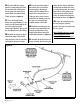
70. Start the engine and let it idle.
The brake valve will close and can be
verified by the muffled sound of a
restricted exhaust pipe.
71. Slowly press the accelerator
pedal. The green LED should turn off
almost immediately (very little
throttle movement) and the solenoid
valve assembly should vent the air
from the brake actuator and the
brake valve should open. Release the
accelerator pedal and the green LED
should again light up. Repeat this
cycle a few times to verify CBC
function.
NOTE: The engine speed
(RPM) should not exceed 1200 rpm
prior to brake disengagement.
72. Allow the vehicle to reach
normal operating temperature. The
brake will remain active until the
vehicle reaches approximately 125°F
engine coolant temperature. Once
the vehicle warms up, the brake will
turn off.
73. Re-install the lower dash panel.
NOTE: Once the vehicle has passed
the initial functional tests outlined
in steps 67-73 the vehicle can be
driven in order to complete the
required functional testing.
74. Obtain a vehicle speed of
approximately 40-45 mph in an area
where speeds of this nature are safe
and traffic is light. Turn the Banks
Brake activation switch to the “ON”
position. Release the throttle. The
brake should activate and the vehicle
will begin to slow. Bring the vehicle
to a safe stop (using the service
brakes). As the vehicle speed drops
below approximately 15 mph the
brake should turn off. Turn the Banks
Brake activation switch to the “OFF”
position.
NOTE: Once the vehicle
has passed the test outlined in
step 73, the installation of the
Banks Brake system is complete
and ready for years of reliable
service.
96986 v.3.0 | 11