
Manual


11. Tighten the two
7
⁄16" bolts at the
ball flange to 15 ft-lbs.
Note: Do not
use an impact wrench on these
fasteners. The wide span of the two-
bolt spherical flange creates sufficient
clamping force when 15 ft-lbs is used.
Exceeding this torque specification
will not increase the sealing
performance.
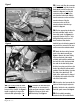
12. Tighten the exhaust clamp that
seals the turbine outlet pipe to the
intermediate pipe.
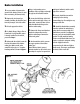
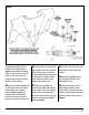
13. Thread the 90-degree hose
fittings provided into all three ports
of the actuator control valve, as
shown in
Figure 3. Mount the valve
to the bracket as shown using the
two 4-40 screws, washers and nylock
nut assemblies.
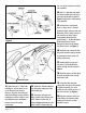
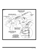
14. Drill a
1
⁄8" pilot hole and mount
the actuator control valve to the upper
passenger side firewall as shown in
Figure 4 using the #12 self-threading
screw provided.
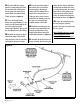
15. On the driver’s side firewall,
there is a large, soft 3
1
⁄2"-diameter
grommet located under the cowl that
allows the vehicle’s wiring harness to
pass from the cab to the engine
compartment. Enlarge the hole
approximately
1
⁄2" to allow the Banks
Brake wiring harness to pass
through. Be careful not to damage
the vehicle harness. See
Figure 5.
16. Inside the cab, remove the dash
kick panel below the steering column
by removing the three screws and
pulling on the panel.
17. Starting with the orange and
blue wires, feed the Banks Brake
harness through the hole located in
Step 15.
18. Route the orange and blue wires
along the underside of the cowl lip
towards the PCM.
19. Locate the white wire with
orange stripe from pin 27 at connector
C2 (white connector). For ‘94-95
vehicles, this wire will be at pin 47 of
the pcm connector. See
Figure 6.
20. Plug the connector on the end
of the orange wire from the Banks
Brake harness into the red t-tap
installed in step 19.
4| 96986 v.3.0
Figure 3
Figure 4