
Manual
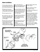

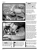
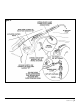

24. (‘94-97 only) Locate the violet
wire with yellow stripe in the factory
harness on the firewall. See
Figure 7.
Install a supplied red t-tap on the
violet wire with yellow stripe. (‘98
only) Locate the tan wire with black
stripe from pin 16 at connector C1
(right most pcm connector). Install a
supplied red t-tap on the tan wire
with black stripe. See
Figure 6.
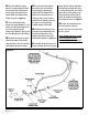
25. (‘94-97 only) Plug the connector
on the end of the gray wire from the
Banks Brake harness into the t-tap
installed in
Step 24. (‘98) Plug the
connector on the end of the gray
wire from the banks brake harness
into the connector on the end of the
extension harness. Plug the
connector on the end of the
extension harness into the t-tap
installed in
Step 24.
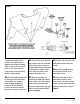
26. Find an appropriate location for
the brake activation switch on the
lower dash panel. See
Figure 9 for
suggested locations. Drill a
1
⁄2" hole
through the dash panel in one of
these locations. Note that the
backside layer of reinforcing material
may need to be removed in the area
used to mount the activation switch.
27. Attach the three wiring harness
leads to the switch assembly per
Figure 9. Remove the outer locking
ring from the shaft of the switch
assembly and install the switch from
the back side of the dash panel with
the notch in the shaft facing down.
Slide the face plate provided over the
shaft of the switch to indicate switch
position. Thread the locking ring onto
the shaft of the switch body. The
depth of the switch may be changed
by adjusting the location of the back
nut on the switch shaft.
28. Secure the wire loom under the
dash and hood using the nylon ties
provided. Inside the cab, reinstall the
dash kick panel removed in
Step 16.
29. Find a suitable mounting
location for the CBC module. Banks
6| 96986 v.3.0
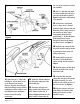
Figure 7
Figure 8