
User Manual


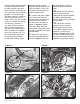
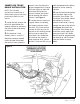
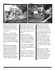

Figure 3 Figure 4
CAUTION: Installation of
the SmartLock Trans Brake
is NOT complete until
Functional Testing,
described on pg. 7 of
this manual, has been
successfully completed.
PNEUMATIC LINE
PRESSURE BOOST
ACTUATOR ASSEMBLY
INSTALLATION:
NOTE: The following
instructions assume that a
Banks Brake system has been
previously installed on the
vehicle.
1. As a precaution,
disconnect the ground of the
battery. If there is more than
one battery, disconnect both.
2. Raise and support the
vehicle.
3. Disconnect the cable from
the kick-down lever on the
side of the transmission case
as shown in Figure 1.
4. Disconnect the return
spring attached to the kick-
down lever as shown in
Figure 2. Save the spring for
reuse later.
5. Loosen the tightening
screw and remove the OEM
kick-down lever as shown in
Figure 3.
6. Remove the bolt shown
in Figure 4 from the
transmission case and install
the line pressure boost
actuator bracket as shown.
Temporarily finger-tighten the
bolt to allow adjustment.
7. Slide the actuator control
lever over the throttle valve
shaft and tighten the bolt.
Re-attach the return spring
to the transmission case
actuator control bracket as
shown in Figure 5. Re-attach
Figure 1
Figure 2
Installation Procedure
97052 v.3.0 | 5