
User Manual


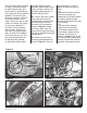
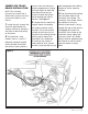
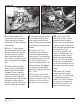
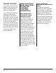

Figure 6
Figure 7
Figure 8
Figure 5
Apply grease
here
the kick down cable removed
in Step 3. Actuate the lever
by hand several times and
ensure there is no binding or
the system will fail to function
properly. Also ensure that
the return spring is sufficient
to return the lever to the
stop. If not, use a pair of side
cutters to shorten the spring
as necessary. Remove
1
⁄4”
at a time until the spring is
able to return the lever to
the stop. Use needle-nosed
pliers to reform the hooked
ends after they are cut. The
rear mounting bracket can
be loosened and rotated
to eliminate binding. Apply
a general purpose water
resistant lithium grease to all
sliding surfaces such as the
actuator shaft extension to
reduce sliding friction.
8. Connect the black rubber
vent hose to the front of
the pneumatic actuator and
the blue silicone hose to
the rear of the actuator as
shown in Figure 6. Route
the hoses away from the
transmission along the frame
rail and up toward the engine
compartment.
9. Secure the vent line in
the engine compartment as
shown in Figure 7. Be sure
the bronze filter is facing
down to allow moisture to
drain.
10. Route the blue silicone
vacuum line along the
underside of the cowl toward
the Banks Brake actuator.
Secure the line with the cable
ties included.
11. Locate the vacuum
supply line running from
the actuator control valve
to the Banks Brake vacuum
actuator. Cut the line as
shown in Figure 8 and install
the vacuum tee. Secure each
vacuum connection with the
supplied spring band clamps.
6 | 97052 v.3.0