
User's Manual


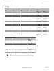


Specifications
Range
The sensor is able to detect a proper object (see Detectable Objects)
from 1 to 40+ m (3.3 to 131.2+ ft), depending on target
Detectable Objects
Objects containing metal, water, or similar high-dielectric materials
Operating Principle
Frequency modulated continuous-wave (FMCW) radar
Operating Frequency
24.00 to 24.25 GHz, ISM Band (varies slightly with model, depending on
national telecom regulations)
Supply Voltage
12 to 30V dc, less than 100 mA, exclusive of load
Supply Protection Circuitry
Protected against reverse polarity and transient overvoltages
Delay at Power-up
Less than 2 seconds
Output Configuration
DIP-Switch A8 selects Dual NPN (default) or PNP; DIP-Switch B7 se-
lects N.O. (default) or N.C. operation; 150mA each
• Zone 1 output: white wire
• Zone 2 output: black wire
Output Protection
Protected against short circuit conditions
Response Time
DIP-Switch-configurable ON/OFF response time
Indicators
Power LED: Green (power ON)
Signal Strength LED: Red, flashes in proportion to signal strength.
Steady on at 4x excess gain. Only indicates signal amplitude, not target
distance.
Output LEDs: Yellow (output energized) / Red (configuration)
Adjustments
DIP-switch-configurable sensing distance, sensitivity, response time, and
output configuration
Construction
Housing: ABS/polycarbonate
Lightpipes: Acrylic
Access Cap: Polyester
Operating Temperature
– 40° to + 65° C (– 40° to + 149° F)
Environmental Rating
IP67
Connections
Integral 5-wire 2 m (6.5 ft) cable or M12 Euro-style QD fitting. QD models
require a mating cordset
Certifications
Telecom approvals pending
Windows
The R-GAGE sensor can be placed behind a glass or a plastic window, but the configuration must be tested and the distance from the sensor to the window must be
determined and controlled prior to installation. There is typically a 20% signal reduction when the sensor is placed behind a window.
Polycarbonate at 4mm thickness performs well in most situations, but the performance depends on filler materials. Thinner (1 to 3 mm) windows have high reflection. The
amount of reflection depends on the material, thickness, and distance from the sensor to the window.
Locate the sensor in a position of minimum reflection from the window, which will repeat every 6.1 mm of distance between the sensor and the window. The positions of
maximum reflection from the window repeat between the minimums, and decrease in effect until the window is approximately 150 mm (5.9 in) away. Consult the factory for
pre-tested window materials which can be used at any distance without issue.
Additionally, the face of the window should be protected from flowing water and ice by use of a flow diverter or hood directly above the window. Falling rain or snow in the
air in front of the window, light water mist, or small beads on the face of the window are typically not an issue. However, a thick, continuous surface of water or ice directly
on the face of the window can be detected as a dielectric boundary.
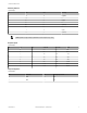
Hookup
shield (QD cordset)
3
1
2
4
5
12-30V dc
Load 1
Load 2
+
–
Wiring Key:
1 = Brown
2 = White
3 = Blue
4 = Black
5 = Gray (Do not connect)
NOTE: Banner recommends that the shield wire (QD cordsets only) be connected to earth ground or dc common. Shielded cordsets are
recommended for all QD models.
R-GAGE™ Q120RA-AF2 Sensor
4 www.bannerengineering.com - tel: 763-544-3164 P/N 157494 Rev. C
FCC ID: UE3Q120RAUS—This device complies with Part 15 of the FCC Rules. Operation is subject to the following two conditions: (1) this device may not cause harmful
interference, and (2) this device must accept any interference received, including interference that may cause undesired operation.