
User's Manual


SureCross™ DX80 Quick Start Guide
6 P/N 128185 Rev B
Banner Engineering Corp. • Minneapolis, MN U.S.A.
www.bannerengineering.com • Tel: 763.544.3164
Quick Start: STEP 1
> Set Network ID & Device/Node Address
The wireless RF network is defined by the Network ID (NID)
assigned to the Gateway and its Nodes. Each device within
this common network must have a unique Device Address
assigned.
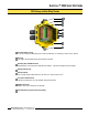
For factory configured kits, the Network ID and Device
Addresses have been assigned. Otherwise, use the Rotary
Switches (shown right) to define both the NID and Device
Address for each device. Follow the steps below to set up
your DX80 network.
Remove rotary switch access covers.
Turn counterclockwise to remove and clockwise to
tighten
On the Gateway, set the Left Rotary Switch to 1.
The factory default NID setting on all devices is 1. Set
to another Network ID when operating more than one
network in the same area.
On all Nodes (within the same network), set the Left
Rotary Switch to 1.
Assign the same NID to all devices within a single
network (hexidecimal 0-F).
On the Gateway, set the Right Rotary Switch to 0.
A Device Address of 0 on the Gateway will display
settings for the Gateway itself. To view settings for
another device on the network, adjust the Right Rotary
Switch on the Gateway to the respective Device
Address.
On the first Node (Device Address = 1), set the Right
Rotary Switch to 1.
Do not change the Device ID for preconfigured kits as
this would affect the factory mapping of the I/O.
On the second Node (Device Address = 2), set the Right
Rotary Switch to 2.
Continue setting the Device Address for each additional
Node using a unique number (..3,4,5).
Install rotary switch access covers. Please refer to the
installation section for IP67 instructions.
A successful RF link is identified by a blinking green LED
1 on each node.
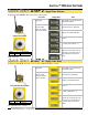
SET NETWORK ID
SET DEVICE ADDRESS
User Action
Display/Status
Notes
Network ID (NID) Device Address
Rotary Switches on
Gateway and Node
Multiple Networks
When more than one network is
operating in the same space, assign
a unique Network ID (NID) to each
network (shown right).
NODE
GATEWAY
GATEWAY
GATEWAY
NODE
NODE
NODE
NODE
NODE
7
NID
8
NID
9
NID
NID: 9
Device: 1
NID: 7
Device: 2
NID: 8
Device: 2
NID: 8
Device: 1
NID: 7
Device: 1
NID: 9
Device: 2