
Instruction Manual


14 P/N 117167 rev. A
Banner Engineering Corp. • Minneapolis, MN U.S.A.
www.bannerengineering.com • Tel: 763.544.3164
MINI-ARRAY
®
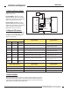
Two-Piece Measuring Light Screen
Appendix A
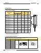
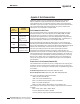
Request Sensor to Transmit all Receiver Channel State (Command 0x64)
This command requests the sensor to provide the state of each optical channel.
The two states for each optical channel are clear (value =0) and blocked (value
=1). Eight optical channels of information are transmitted in each data byte. The
first data byte contains the information for the eight optical channels located
closest to the sensor cable end cap. The following data bytes will contain
information for eight successive optical channel sections. For a data byte, each bit
of the data byte is directly related to the status of an individual optical channel. For
example, if the first eight optical channels have the following states:
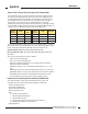
Then the data byte would be 0x2D. If the array has 32 optical channels, then there
would be four data bytes representing the status of all 32 optical channels. Assume
that the sensor ID is 0x41 and the following serial transmission occurs:
Transmit string to sensor: 0xF4, 0x41, 0x64, 0x00, 0x66, 0xFE
Receive string from sensor: 0xF4, 0x41, 0x64, 0x04, 0x2D, 0x03, 0xC0, 0x81,
0xF1, 0xFC
This receive string would be interpreted as follows:
0xF4 is the start-of-header byte
0x41 is the sensor-identification byte
0x64 is the command requesting the sensor optical channel information
0x04 is the number of data bytes
0x2D optical channels 1, 3, 4, 6 are blocked; optical channels 2, 5, 7, 8 are
clear
0x03 optical channels 9 and 10 are blocked; optical channels 11-16 are clear
0xC0 optical channels 17-22 are clear; optical channels 23 and 24 are blocked
0x81 optical channels 25 and 32 are blocked; optical channels 26-31 are clear
The last two bytes are the check sum in low-byte, high-byte order
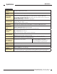
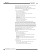
Request Sensor to Transmit System Status Information (Command 0x66)
This command will be used to extract information about the sensor. The
information that can be received includes the following six data bytes:
Number of Emitter Channels
First Emitter Failed Channel
Number of Receiver Channels
First Bad Receiver Channel
State
0 – System is working properly
1 – System detects weak alignment
2 – System detects dirty lens
3 – System detects degraded emitter (faulty emitter element)
4 – System detects emitter is not functioning
Degraded Channel
Optical
Channel
Position
Status
Binary
Value
Optical
Channel
Position
Status Binary Value
1 blocked 1 5 clear 0
2 clear 0 6 blocked 1
3 blocked 1 7 clear 0
4 blocked 1 8 clear 0