
Installation guide


Installation Guide
Advanced sensor with dual digital displays for use with plastic and glass fiber optic assemblies.
For complete technical information about this product, including dimensions, accessories, and specifications, see
www.bannerengineering.com and search
161999.
Overview
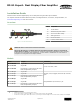
Figure 1. DF-G1 Model Features
1 Output LED
2 LO/DO Switch
3 RUN/PRG/ADJ Mode Switch
4 Lever Action Fiber Clamp
5 Red Signal Level
6 Green Threshold
7 +/SET/- Rocker Button
WARNING: Not To Be Used for Personnel Protection
Never use this device as a sensing device for personnel protection. Doing so could lead to
serious injury or death. This device does not include the self-checking redundant circuitry necessary
to allow its use in personnel safety applications. A sensor failure or malfunction can cause either an
energized or de-energized sensor output condition.
Models
Model Outputs Connector
1
DF-G1-NS-2M Single NPN
2 m (6.5 ft) cable, 4-wire
DF-G1-PS-2M Single PNP
DF-G1-KS-2M Dual outputs, 1 push-pull IO-Link and 1
PNP (complementary outputs)
DF-G1-NS-Q5 Single NPN
150 mm (6 in) PVC pigtail, M12 Euro QD connector,
4-pin
DF-G1-PS-Q5 Single PNP
DF-G1-KS-Q5 Dual outputs, 1 push-pull IO-Link and 1
PNP (complementary outputs)
DF-G1-NS-Q7 Single NPN
Integral M8 Pico QD connector, 4-pin
DF-G1-PS-Q7 Single PNP
DF-G1-KS-Q7
Dual outputs, 1 push-pull IO-Link and 1
PNP (complementary outputs)
1
Connector options:
•
A model with a QD connector requires a mating cordset .
• For 9 m cable, change the suffix 2M to 9M in the 2 m model number (example, DF-G1-NS-9M).
• For 150 mm (6 in) PVC pigtail, M8 Pico QD connector, 4-pin change the suffix 2M to Q3 in the 2 m model number (example, DF-G1-NS-Q3).
DF-G1 Expert
™
Dual Display Fiber Amplifier
Original Document
161275 Rev. C
1 April 2014
161275