DF-G1 Expert™ Dual Display Fiber Amplifier Instruction Manual Original Instructions 161999 Rev.
DF-G1 Expert™ Dual Display Fiber Amplifier Contents 1 Product Description ....................................................................................................... 3 1.1 Models ....................................................................................................................................3 1.2 Overview ................................................................................................................................ 4 1.3 Top Panel Interface ................
DF-G1 Expert™ Dual Display Fiber Amplifier 1 Product Description Advanced sensor with dual digital displays for use with plastic and glass fiber optic assemblies • • • • • • • • • • • Easy to read dual digital displays show both signal level and threshold simultaneously Lever action fiber clamp provides stable, reliable, and trouble-free fiber clamping Simple user interface ensures easy sensor set-up and programming via displays and switches/buttons, remote input teach wire, or IO-Link Expert TEACH and
DF-G1 Expert™ Dual Display Fiber Amplifier 1.2 Overview The DF-G1 is an easy-to-use, DIN-rail-mountable fiber optic sensor. It provides high-performance sensing in low-contrast applications. The sensor’s compact housing has dual digital displays (Red/Green) and a bright output LED for easy programming and status monitoring during operation. The sensor features a single discrete output, either NPN or PNP, by model.
DF-G1 Expert™ Dual Display Fiber Amplifier Output LED The output LED provides a visible indication when the output is activated.
DF-G1 Expert™ Dual Display Fiber Amplifier 2 Installation Instructions 2.1 Mounting Instructions Mount on a DIN Rail 1. Hook the DIN rail clip on the bottom of the DF-G1 over the edge of the DIN rail (1). 2. Push the DF-G1 up on the DIN rail (1). 3. Pivot the DF-G1 onto the DIN rail, pressing until it snaps into place (2). Mount to the Accessory Bracket 1. Position the DF-G1 in the SA-DIN-BRACKET. 2. Insert the supplied M3 screws. 3. Tighten the screws. Remove from a DIN rail 1.
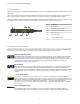
DF-G1 Expert™ Dual Display Fiber Amplifier TO FIBERS TO SENSOR Fiber Outer Diameter (mm) Adapter Color Ø 1.0 Black Ø 1.3 Red Ø 2.2 No adapter needed When connecting coaxial-type fiber assemblies to the amplifier, install the solid core fiber to the LED emitting port, and the multi-core fiber to the PD receiving port for most reliable detection. RECEIVER Multi-core fiber Single-core fiber TRANSMITTER 2.
DF-G1 Expert™ Dual Display Fiber Amplifier 3 Run Mode Run mode allows the sensor to operate normally and prevents unintentional programming changes. The +/SET/- rocker button is disabled during RUN mode, except when using Window SET, see Window SET on page 17.
DF-G1 Expert™ Dual Display Fiber Amplifier 4 Program Mode Program (PRG) mode allows the following settings to be programmed in the DF-G1 (refer to Figure 2 on page 9 and Figure 4 on page 12 for programming). Figure 2.
DF-G1 Expert™ Dual Display Fiber Amplifier 4.1 TEACH Selection The DF-G1 can be programmed for one of the following TEACH/SET methods: • Two-Point TEACH • Dynamic TEACH • Window SET • Light SET • Dark SET • Calibration SET NOTE: A TEACH Selection must be selected by programming before TEACH/SET methods can be used. 4.
DF-G1 Expert™ Dual Display Fiber Amplifier • Severe contamination/changes in the taught condition can prevent the Auto Thresholds algorithm from optimizing the threshold(s). If this occurs, the DF-G1 will enter a Threshold Alert or Threshold Error state. See Troubleshooting on page 24 for more explanation. 4.5 Delays/Timers ON/OFF Delays and ON/OFF One-Shot timers can be programmed between 1 9999 ms (a value of 0 disables the delay/ timer).
DF-G1 Expert™ Dual Display Fiber Amplifier 5 Remote Input (not available on IO-Link models) The remote input may be used to perform TEACH/SET methods and to program the sensor remotely. Connect the white input wire of the sensor to ground (0 V dc), with a remote switch connected between them. Pulse the remote input according to the diagram shown in Figure 4 on page 12. Follow the instructions in the TEACH/SET sections in Adjust Mode on page 13 to perform a TEACH/SET method.
DF-G1 Expert™ Dual Display Fiber Amplifier 6 Adjust Mode Sliding the RUN/PRG/ADJ mode switch to the ADJ position allows the user to perform Expert TEACH/SET methods and Manual Adjustment of the threshold(s). 6.1 Two-Point TEACH • • Establishes a single switching threshold Threshold can be adjusted using "+" and "-" rocker button (Manual Adjust) Two-Point TEACH is used when two conditions can be presented statically to the sensor.
DF-G1 Expert™ Dual Display Fiber Amplifier Method Action Result SET Button 2 Set the Mode switch to ADJ. Remote Input 3 No action is required; sensor is ready for the Two-Point TEACH method Display: Red - Signal Level; Green Threshold 2. Teach the first condition. Method Action Result SET Button a. Present the first condition. Display: Flashes "2Pt tch" then holds on "1234 2nd" b. Click the SET rocker button T Remote Input a. Present the first condition. b. Single-pulse the remote input.
DF-G1 Expert™ Dual Display Fiber Amplifier 6.2 Dynamic TEACH • • • Teaches on-the-fly Establishes a single switching threshold Threshold can be adjusted using "+" and "-" rocker button (Manual Adjust) Dynamic TEACH is best used when a machine or process may not be stopped for teaching. The sensor learns during actual sensing conditions, taking multiple samples of the light and dark conditions and automatically setting the threshold at the optimum level (see Figure 6 on page 15).
DF-G1 Expert™ Dual Display Fiber Amplifier Method Action Result SET Button Click the SET rocker button Display: Flashes "dYn tch" then holds on "1234 dYn" Remote Input Single-pulse remote input T 3. Present ON and OFF Conditions. Method Action Result SET Button Present ON and OFF conditions Display: Red - Signal Level; Green Threshold Remote Input Present ON and OFF conditions 4. Exit Dynamic TEACH.
DF-G1 Expert™ Dual Display Fiber Amplifier 6.
DF-G1 Expert™ Dual Display Fiber Amplifier Method Action • • Result Present sensing condition Click the SET rocker button SET Button Remote Input Threshold Condition Accepted • • Present sensing condition Single-pulse the remote input T Displays read "wInd SEt" then alternate "PASS" with % Offset10; Sensor returns to Adjust mode Threshold Condition Not Accepted Displays read "wInd SEt" then alternate "FAIL" with minimum % Offset10 for sensing condition; Sensor returns to Adjust mode 3.
DF-G1 Expert™ Dual Display Fiber Amplifier A single sensing condition is presented, and the sensor positions a threshold a programmable % offset below the presented condition. When a condition darker than the threshold is sensed, the output either turns ON or OFF, depending on the LO/DO switch setting (see LO/DO Switch in Top Panel Interface on page 4).
DF-G1 Expert™ Dual Display Fiber Amplifier Method Action • • Result Present sensing condition Click the SET rocker button Threshold Condition Accepted SET Button Remote Input • • Present sensing condition Single-pulse the remote input T Displays read "Lt SEt" then alternate "PASS" with % Offset13; Sensor returns to Adjust mode Threshold Condition Not Accepted Displays read "Lt SEt" then alternate "FAIL" with minimum % Offset13 for sensing condition; Sensor returns to Adjust mode 3.
DF-G1 Expert™ Dual Display Fiber Amplifier Threshold position adjusted by Manual Adjust Sensor positions threshold a programmable % offset above the presented condition Output OFF Darkest (no signal) Output ON Condition Presented Most Light (saturated signal) Figure 10.
DF-G1 Expert™ Dual Display Fiber Amplifier Method Action • • Result Present sensing condition Click the SET rocker button SET Button Threshold Condition Accepted • • Remote Input Present sensing condition Single-pulse the remote input Displays read "dr SEt" then alternate "PASS" with % Offset16; Sensor returns to Adjust mode T Threshold Condition Not Accepted Displays read "dr SEt" then alternate "FAIL" with minimum % Offset16 for sensing condition; Sensor returns to Adjust mode 3.
DF-G1 Expert™ Dual Display Fiber Amplifier • • Press "+" to increase; press "-" to decrease ◦ GREEN display shows the switching threshold value ◦ 2 seconds after adjustment, the GREEN display will flash 3 times to confirm Slide Mode switch to RUN to complete operation Remember: Auto Thresholding is automatically disabled in Calibration SET Follow these steps to perform a Calibration SET: Note: TEACH Selection must be programmed to CAL SEt (see Program Mode on page 9 ) 1.
DF-G1 Expert™ Dual Display Fiber Amplifier 6.7 Troubleshooting 6.7.1 Manual Adjustments Disabled Manual adjustments are disabled when Auto Thresholds are ON. If a manual adjustment is attempted while Auto Thresholds are ON, the Green display will flash . 6.7.2 Percent Minimum Difference after TEACH The Two-Point and Dynamic TEACH methods will flash a % minimum difference on the displays after a PASS or FAIL.
DF-G1 Expert™ Dual Display Fiber Amplifier 7 IO-Link Interface IO-Link is a point-to-point communication link between a master device and sensor. It can be used to automatically parameterize sensors and transmit process data. For the latest IO-Link protocol and specifications, please visit the web site at http://www.io-link.com. The IO-Link IODD package is contained on the Banner IO-Link Device Description Resource CD (P/N 18491). For the latest IODD files, please refer to the Banner Website at http://www.
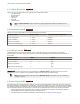
DF-G1 Expert™ Dual Display Fiber Amplifier 8 Specifications Sensing Beam 660 nm visible red Supply Voltage NPN/PNP models: 10 to 30 V dc Class 2 (10% max ripple) IO-Link models: 18 to 30 V dc (10% max ripple) Power and Current Consumption (exclusive of load) Standard display mode: 960 mW, Current consumption < 40 mA at 24 V dc ECO display mode: 720 mW, Current consumption < 30 mA at 24 V dc Supply Protection Circuitry Protected against reverse polarity, overvoltage, and transient voltages Delay at Power Up
DF-G1 Expert™ Dual Display Fiber Amplifier 8.1 Excess Gain Curves Opposed Mode Diffuse Mode 0.25 mm (0.01 in) Diameter Fibers PBT16U PIT16U 1000 10000 XLR LR HS/STD XLR LR HS/STD 100 EXCESS GAIN EXCESS GAIN 1000 100 10 10 1 1 0.1 1 10 0.1 100 1 10 100 DISTANCE (mm) DISTANCE (mm) 0.51 mm (0.02 in) Diameter Fibers PBT26U PIT26U 100000 EXCESS GAIN 10000 EXCESS GAIN 10000 XLR LR HS/STD 1000 100 XLR LR HS/STD 1000 100 10 10 1 0.
DF-G1 Expert™ Dual Display Fiber Amplifier Opposed Mode Diffuse Mode 1.02 mm (0.04 in) Diameter Fibers PBT46U PIT46U 10000 100000 XLR LR HS/STD XLR LR HS/STD 1000 EXCESS GAIN EXCESS GAIN 10000 1000 100 10 10 1 100 1 10 100 1 1000 0.1 1 DISTANCE (mm) 10 100 1000 DISTANCE (mm) 1.52 mm (0.06 in) Diameter Fibers PBT66U PIT66U 100000 10000 10000 1000 1000 EXCESS GAIN EXCESS GAIN XLR LR HS/STD XLR LR HS/STD 100 10 100 10 1 1 1 10 100 1000 0.
DF-G1 Expert™ Dual Display Fiber Amplifier 8.2 Beam Patterns Opposed Mode Diffuse Mode 0.25 mm (0.01 in) Diameter Fibers PBT16U PIT16U 4 30 XLR LR HS/STD BEAM WIDTH (mm) BEAM WIDTH (mm) 20 10 0 -10 -20 -30 XLR LR HS/STD 3 2 1 0 -1 -2 -3 -4 0 5 10 15 20 25 30 35 40 45 50 0 2 4 6 8 10 12 DISTANCE (mm) DISTANCE (mm) 0.51 mm (0.
DF-G1 Expert™ Dual Display Fiber Amplifier Opposed Mode Diffuse Mode 1.02 mm (0.04 in) Diameter Fibers PBT46U PIT46U 80 400 XLR LR HS/STD XLR LR HS/STD 60 40 200 BEAM WIDTH (mm) BEAM WIDTH (mm) 300 100 0 -100 -200 20 0 -20 -40 -60 -300 -80 -400 0 100 200 300 400 500 600 700 0 800 20 40 60 80 100 120 140 160 180 200 DISTANCE (mm) DISTANCE (mm) 1.52 mm (0.
DF-G1 Expert™ Dual Display Fiber Amplifier 8.
DF-G1 Expert™ Dual Display Fiber Amplifier 9 Accessories SA-DIN-CLAMP • • Pair of metal DIN rail end stops; slide onto DIN rail at either side of DF-G1 sensor stack Combination (#2 Phillips, #8 standard slotted) set screw 9.1 mm (0.63") 9.1 mm (0.36") 45.0 mm (1.77") SA-DIN-BRACKET • 10 1 plastic bracket with mounting screws SA-DIN-BRACKET-10 • Package of 10 plastic brackets with mounting screws 35 DIN-35-..
DF-G1 Expert™ Dual Display Fiber Amplifier 4-Pin Threaded M8/Pico-Style Cordsets Model Length PKG4M-2 2.00 m (6.56 ft) PKG4M-5 5.00 m (16.4 ft) PKG4M-9 9.00 m (29.5 ft) Style Dimensions Pinout 35 Typ. 4 Straight PKW4M-2 2.00 m (6.56 ft) PKW4M-5 5.00 m (16.4 ft) PKW4M-9 9.00 m (29.5 ft) 3 ø 9.5 M8 x 1 2 1 1 2 3 4 = = = = Brown White Blue Black 28 Typ. 20 Typ. Right Angle M8 x 1 ø 9.5 4-Pin Snap-on M8/Pico-Style Cordsets Model Length Style Dimensions Pinout PKG4-2 2 m (6.
DF-G1 Expert™ Dual Display Fiber Amplifier 10 Banner Engineering Corp Limited Warranty Banner Engineering Corp. warrants its products to be free from defects in material and workmanship for one year following the date of shipment. Banner Engineering Corp. will repair or replace, free of charge, any product of its manufacture which, at the time it is returned to the factory, is found to have been defective during the warranty period.