
User Manual


Power General
2
Supply Protection Circuitry
Protected against transient voltages and reverse polari-
ty
Operating Conditions
Temperature: 0° to +50°C (+32° to 122°F)
Max. Relative Humidity: 90% @ +50°C (non-condens-
ing)
Output Configuration
Output Configuration
ES-FA-9AA: 3 normally open (N.O.) output channels
ES-FA-11AA: 2 normally open (N.O.) output channels
and 1 normally closed (N.C.) auxiliary output
Contacts
AgNi, 5 μm gold-plated
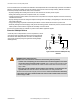
Each normally open output channel is a series connection of con-
tacts from two forced-guided (mechanically linked) relays, K1-K2.
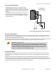
The normally closed Aux. output channel of the ES-FA-11AA is a
parallel connection of contacts from two forced-guided relays, K1-
K2.
Low Current Rating: The 5 μm gold-plated contacts allow the
switching of low current/low voltage. In these low-power applica-
tions, multiple contacts can also be switched in series (e.g., “dry
switching”). To preserve the gold plating on the contacts, do not
exceed the following max. values at any time:
Minimum Maximum
Voltage 1V ac/dc 60V
Current 5 mA ac/dc 300 mA
Power 5 mW (5 mVA) 7 W (7 VA)
High Current Rating: If higher loads must be switched through
one or more of the contacts, the minimum and maximum values of
the contact(s) changes to:
Minimum Maximum
Voltage 15V ac/dc 250V ac/dc
Current 30 mA ac/dc ES-FA-9AA: 6A
ES-FA-11AA: 7A
Power 0.45 W (0.45 VA) ES-FA-9AA: 200 W (1,500 VA)
ES-FA-11AA: 200 W (1,750 VA)
Mechanical life
> 20,000,000 operations
Electrical life (switching cycles of the output contacts,
resistive load)
150,000 cycles @ 1,500 VA; 1,000,000 cycles @ 450
VA; 2,000,000 cycles @ 250 VA; 5,000,000 cycles @
125 VA
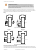
NOTE: Transient suppression is recommended when switching in-
ductive loads. Install suppressors across load. Never install sup-
pressors across output contacts (see Wiring of Arc Suppressors
warning in Auxiliary Monitor Contact (Model ES-FA-11AA Only) on
page 8).
Output Response Time
25 milliseconds typical
Input Requirements
Safety input switch: Dual-Channel (contacts) hookup –
10 to 20 mA steady state @ 12V dc. NOTE: Inputs are
designed with a brief contact-cleaning current of 100
mA when initially closed.
Safety input switch: Single-Channel hookup – 40 to
100 mA @ 24V ac/dc +/- 10%; 50/60 Hz
Reset switch: 20 mA @ 12V dc, hard contact only
Minimum OFF-State Recovery Time
250 ms
Design Standards
Cat. 4 PL e per EN ISO 13849-1; SIL 3 per IEC 61508
and IEC 62061
Certifications
ES-FA-9AA and ES-FA-11AA E-Stop Safety Modules
P/N 060606 Rev. F www.bannerengineering.com - tel: 763-544-3164 11