
User Manual


Connection of Safety Switches
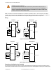
The Safety Module may be used to monitor safety interlocking
switches that determine the position of a guard or gate. To achieve
Category 4 operation per ISO 13849-1 (EN 954-1), two positive-open-
ing safety switches must operate concurrently when the guard or gate
is opened.
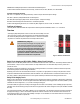
The Safety Module verifies concurrent opening of two contacts – one
from each safety switch. Reset of the Safety Module is not possible if
one switch fails to open or if a short circuit between the safety inter-
locking switches occurs.
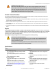
S12S22S11 S21
Safety Gate or Guard with
end-of-travel stops and two
individually mounted
Safety Interlocking Switches
OPEN
Figure 3. Wiring using contacts from two safety switches
Connection of Reset Switch
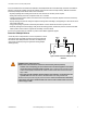
The reset circuit switch can be any mechanical switch, such as a normally open momentary switch, or a two-position key switch. The
reset switch must be capable of reliably switching 8 to 12V dc at 10 to 15 milliamps. As shown in the hookup drawings, the reset switch
connects between Safety Module terminals S33 and S11.
The reset switch must be located outside of – and not be accessible from – the area of dangerous motion, and must be positioned so that
any area of dangerous motion may be observed by the switch operator during the reset procedure. See warning below.
WARNING: Reset Switch Location
All reset switches must be accessible only from outside, and in full view of, the hazardous area.
Reset switches must also be out of reach from within the safeguarded space, and must be protec-
ted against unauthorized or inadvertent operation (for example, through the use of rings or guards). If
any areas are not visible from the reset switch(es), additional means of safeguarding must be provided.
Failure to do so could result in serious bodily injury or death.
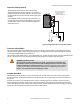
Automatic Reset Mode
The Safety Module may be configured (via hookup) for automatic reset. If no MSC contacts are monitored, install a jumper between
terminals S33 and S34. The Safety Module will reset (and its outputs energize) as soon as the switch returns to its armed (closed-con-
tact) position.
Automatic reset is useful for some automated processes. However, if automatic reset is used, it is necessary to provide a means of
preventing resumption of hazardous machine motion, until an alternate reset procedure is performed. The alternate procedure must in-
clude a reset/restart switch, located outside the area of dangerous motion, which is positioned so that any area of dangerous motion may
be observed by the switch operator during the reset procedure. See Warning below.
ES-FA-9AA and ES-FA-11AA E-Stop Safety Modules
6 www.bannerengineering.com - tel: 763-544-3164 P/N 060606 Rev. F