
User Manual
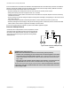

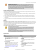

WARNING: Reset Routine Required
U.S. and international standards require that a reset routine be performed after clearing the cause of a
stop condition (for example, arming an E-stop button, closing an interlocked guard, etc.). Allowing the
machine to restart without actuating the normal start command/device can create an unsafe condi-
tion which could result in serious injury or death.
NOTE: The minimum time required for the Module to be in a STOP or OFF condition is 250 ms. This “recovery time” (OFF-state) is
required for the internal circuitry of the Safety Module to normalize, allowing a reliable reset to occur. A lockout occurs if the Module is
cycled too quickly. To clear the lockout, the Module must be recycled, meeting the minimum OFF time requirements.
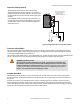
Wiring
24V ac/dc
MSC1
E-Stop
Switch
E-Stop
Switch
Reset
MSC3
MSC2
See WARNING
Below
MSC
Monitor
Contacts
or
Jumper
A2
A1
S34
S33
S21
S11
S12
S22
dc common
+V
ES-FA-9AA
24V ac/dc
Auto Reset Manual Reset
A2
(No Connection)
A1
S34
S11
S33
MSC1 MSC2 MSC3
S22
S12
S21
dc common
+V
ES-FA-9AA
Figure 4. Dual-Channel E-Stop Applications
24V ac/dc
MSC1 MSC3
MSC2
See Interfacing MSCs
Warning
MSC
Monitor
Contacts
or
Jumper
A2
A1
S34
S33
S21
S11
S12
S22
dc common
+V
ES-FA-9AA
24V ac/dc
Auto Reset Manual Reset
A2
(No Connection)
Reset
A1
S34
S11
S33
MSC1 MSC2 MSC3
S22
S12
S21
dc common
+V
ES-FA-9AA
E-Stop
Switch
E-Stop
Switch
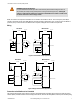
Figure 5. Single-Channel E-Stop Applications
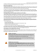
Connection to the Machine to be Controlled
The machine hookup diagram shows a generic connection of the Safety Module's redundant output circuits to the master stop control
elements (MSCs). An MSC is defined as an electrically powered device, external to the Safety Module, which stops the machinery being
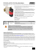
ES-FA-9AA and ES-FA-11AA E-Stop Safety Modules
P/N 060606 Rev. F www.bannerengineering.com - tel: 763-544-3164 7