
User Manual


*
*
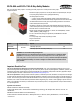
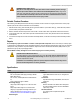
L2
MSC1
MSC2
Machine
Master Stop
Control Elements
*Arc suppressors
(see WARNING)
K1
A
6A max.
6A max.
6A max.
K2
A
K1
B
K2
B
K1
C
K2
C
*
MSC3
13
14
23
24
33 34
L1
Machine
Control
Circuits
ES-FA-9AA
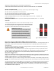
*
*
L2
MSC1
MSC2
Machine
Master Stop
Control Elements
*Arc suppressors
(see WARNING)
K1
A
7A max.
7A max.
7A max.
K2
A
K1
B
K2
B
K1
C
K2
C
13 14
23 24
31 32
L1
Machine
Control
Circuits
ES-FA-11AA
Feedback
(optional)
Figure 6. Machine Control Circuit Connections
Initial Checkout Procedures
CAUTION: Disconnect Power Prior to Checkout
Before performing the initial checkout procedure, make certain all power is disconnected from the
machine to be controlled.
Dangerous voltages may be present along the Safety Module wiring barriers whenever power to the ma-
chine control elements is ON. Exercise extreme caution whenever machine control power is or may
be present. Always disconnect power to the machine control elements before opening the enclo-
sure housing of the Safety Module.
1. Remove power from the machine control elements.
2. Ensure the safety device is in a STOP or "open-contact" state (e.g., actuate the E-stop switch to open its contacts).
3. Apply power to the Safety Module at terminals A1 and A2 (see wiring diagrams). Verify that only the Input Power indicator (see Figure
1. Features and Terminals on page 2) is ON. If either input channel 1 (K1) or input channel 2 (K2) indicators are ON at this point,
disconnect the input power and check all wiring. Return to step 2 after the cause of the problem has been corrected.
4. Reset or otherwise cause the safety device to reach an ON or "closed-contact" state (e.g., arm the E-stop switch to close its con-
tacts).
Automatic reset: Ch1 (K1) and Ch2 (K2) indicators should come ON, and the safety output contacts should close.
Manual reset: From an open condition, close the reset switch for approximately ¼ second, and then re-open. The Ch1 (K1) and Ch2
(K2) indicators should both come ON steady at this time. If either indicator comes ON before the reset switch is opened, disconnect
the input power and check all wiring. Return to step 2 after correcting the problem.
5. Cause the safety device to generate a STOP or "open-contact" state (e.g., actuate the E-stop switch to open its contacts). The Ch1
(K1) and Ch2 (K2) indicators should turn OFF simultaneously. If either indicator remains ON, disconnect the input power and check
all wiring. Return to step 2 after the cause of the problem has been corrected.
6. If more than one safety device is series-connected to the Safety Module, run the above checkout procedure individually for EACH
device.
7. Close and secure the enclosure in which the Safety Module is mounted. Apply power to the machine control elements and perform
the Periodic Checkout Procedure.
ES-FA-9AA and ES-FA-11AA E-Stop Safety Modules
P/N 060606 Rev. F www.bannerengineering.com - tel: 763-544-3164 9