
User Manual


2. Verify that the System is in RUN mode with the Status Clear indicator ON steady Green. A manual reset may be required in Latch
mode.
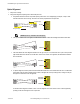
3. Pass the specified test piece through the defined area in three paths: near the emitter, near the receiver, and midway between the
emitter and receiver.
4. During each pass, while the test piece is interrupting the defined area, verify:
• Trip Output Operation: The Status Blocked indicator must turn ON Red and remain ON for as long as the test piece remains in
the defined area (and the Status Clear indicator OFF during the same time). If not, the installation has failed the trip test. When
the test piece is removed from the defined area, the Status Clear indicator must turn ON Green and the Status Blocked indica-
tor must go OFF.
• Latch Output Operation: The Status Blocked indicator must turn ON Red and remain ON for as long as the test piece remains
in the defined area (and the Status Clear indicator OFF during the same time). Both Yellow indicators must remain ON steady,
unless the top or bottom beam is blocked. If the top (synch) beam is blocked, both Alignment indicators will go OFF.
If the Yellow Alignment indicators begin to flash at any time while the test piece is interrupting the defined area, the installation
has failed the trip test. Check for correct sensor orientation and reflective surfaces. Do not continue until the situation is correc-
ted. In Latch Output Operation, the Status Blocked indicator will remain ON until a manual reset is performed (both Yellow
Alignment indicators will be flashing).
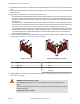
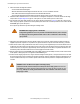
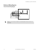
5. If mirrors are used in the application: Test the defined area on each leg of the sensing path (for example, emitter to mirror, between
mirror and receiver, see Figure 15. Trip Test with corner mirror on page 33 ).
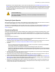
A
C
B
Figure 14. Trip Test
A
C
B
D
Figure 15. Trip Test with corner mirror
A Emitter
B Test Piece
C Receiver
A Emitter
B Mirror
C Receiver
D Test Piece
6. If the EZ-SCREEN Type 2 System passes all checks during the trip test, go on to EZ-SCREEN Type 2 Electrical Interface to the
Guarded Machine on page 34.
WARNING: If Trip Test Indicates a Problem
If the EZ-SCREEN Type 2 System does not respond properly to the trip test,do not attempt to use the
System.
If this occurs, the System cannot be relied on to stop dangerous machine motion when a person or object
enters the defined area.
Increased risk of harm could result.
EZ-SCREEN® Type 2 Light Screen Instruction Manual
122452 rev. B www.bannerengineering.com - tel: 763-544-3164 33