
User Manual
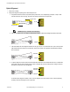


• No Monitoring. Use this configuration initially, in order to perform the initial checkout; see EZ-SCREEN Type 2 Light Screen Initial
Checkout on page 28. If No Monitoring is selected, the user must ensure that any single failure of the external devices does not result
in a hazardous condition and, in such a case, a successive machine cycle will be prevented. To configure the System for No Monitor-
ing, simply do not interface the Power Monitoring circuit (i.e., the four forced-guided normally open contacts from each device) and
connect directly to +24V dc.
CAUTION: EDM Monitoring
If the system is configured for "No Monitoring,", it is the user’s responsibility to ensure that this does not
create a hazardous situation.
Preparing for System Operation
After the initial trip test has been accomplished, and the OSSD safety outputs and EDM connections have been made to the machine to
be controlled, the EZ-SCREEN Type 2 is ready for testing in combination with the guarded machine.
The operation of the EZ-SCREEN Type 2 with the guarded machine must be verified before the combined System and machine may be
put into service. To do this, a Qualified Person must perform the Commissioning Checkout Procedure described in Commissioning
Checkout on page 38.
Commissioning Checkout
Perform this checkout procedure as part of System installation (after the System has been interfaced to the guarded machine), or when-
ever changes are made to the System (either a new configuration of the EZ-SCREEN Type 2 or changes to the machine). A Qualified
Person must perform the procedure; checkout results should be recorded and kept on or near the guarded machine as required by appli-
cable standards.
To prepare the System for this checkout:
1. Examine the guarded machine to verify that it is of a type and design compatible with the EZ-SCREEN Type 2 System. See
Examples: Inappropriate Applications on page 8 for a list of misapplications.
2. Verify that the minimum safety distance from the closest danger point of the guarded machine to the defined area is not less than
the calculated distance, per Calculating the Safety Distance (Minimum Distance) on page 13 of this manual.
3. Verify that:
• Access to any dangerous parts of the guarded machine is not possible from any direction not protected by the EZ-SCREEN
Type 2 System, hard guarding, or supplemental safeguarding.
• It is not possible for a person to stand between the defined area and the dangerous parts of the machine.
• Supplemental safeguarding and hard guarding, as described by the appropriate safety standards, are in place and functioning
properly in any space (between the defined area and any hazard) which is large enough to allow a person to stand undetected
by the EZ-SCREEN Type 2.
4. Verify that all reset switches are mounted outside and in full view of the guarded area, out of reach of anyone inside the guarded
area, and that means of preventing inadvertent use is in place.
5. Examine the electrical wiring connections between the EZ-SCREEN Type 2 FSD outputs and the guarded machine’s control ele-
ments to verify that the wiring meets the requirements stated in FSD Interfacing Connections on page 35.
6. Inspect the area near the defined area (including work pieces and the guarded machine) for reflective surfaces (see Adjacent Re-
flective Surfaces on page 19). Remove the reflective surfaces if possible by relocating them, painting, masking or roughening them.
Remaining problem reflections will become apparent during the Trip Test in step 10.
7. Apply power to the EZ-SCREEN Type 2 System. Verify that power to the guarded machine is OFF. Remove all obstructions from
the defined area. Latch Output models: (Manual Power-Up), both Alignment indicators will be flashing Yellow. Perform a manual
reset (open the reset switch for 1/4 second, then close it).
EZ-SCREEN® Type 2 Light Screen Instruction Manual
38 www.bannerengineering.com - tel: 763-544-3164 122452 rev. B