
Modulated Amplifiers Specification Sheet

SUPPLY VOLTAGE: 10 to 30V dc at less than 20 milliamps (ex-
clusive of load); 10% maximum ripple.
OUTPUT CONFIGURATION: two open-collector NPN (current
sinking) transistor (solid-state) switches; one normally open (light
operate) and one normally closed (dark operate); 150 milliamps maxi-
mum, each output. Saturation voltage less than 0.5V dc at 10 milliamp
load. Off-state leakage current less than 1 microamp.
RESPONSE SPEED: 1 millisecond ON and OFF.
REPEATABILITY: 0.3 millisecond.
SENSOR LEAD LENGTH: 15 feet (4,5 m) maximum.
ADJUSTMENT: GAIN adjustment (single-turn potentiometer;
adjust with small at-blade screwdriver).
INDICATOR: exclusive Banner Alignment Indicator Device
(AID™) system lights a red LED indicator whenever the sensor "sees"
its own modulated light source, and pulses at a rate proportional to the
strength of the received light signal.
CONSTRUCTION*: totally encapsulated plug-in package with
molded VALOX
®
housing. Gold-ashed connection pins.
OPERATING TEMPERATURE:
0 to +70 degrees C (32 to +158 degrees F).
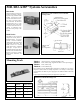
*A Dimension Drawing appears on page 3.
MICRO-AMP
®
Model MA3 Specications
Model MA3P has the same specications and performance as the MA3 amplier, except that the MA3P has complementary PNP outputs in
place of the MA3's NPN conguration.
OUTPUT: two PNP transistors, complementary outputs; one normally open (light operate) and one normally closed (dark operate). 150 mil-
liamps maximum, each output. Saturation voltage is less than 1V dc at 10 milliamps. Off-state leakage current is less than 1 microamp.
Printed in USA
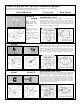
Hookup Diagram, MA3 Amplier
Functional Schematic, MA3 Amplier
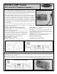
Banner MICRO-AMP
®
modules MA3 and MA3P are modulated ampliers designed
for use with the miniature SP100 Series remote sensors. Miniature photoelectric
sensors, such as the SP100s, have traditionally been used as non-modulated devices with
very limited response. These specially-engineered ampliers bring about a dramatic
improvement in the optical performance of miniature remote sensors.
MICRO-AMP modules are powered by 10 to 30 volts dc, and feature the patented
Banner Alignment Indicator Device (AID™) signal strength LED. Sensor sensitivity
is adjustable via a top-mounted GAIN potentiometer. Model MA3 has complemen-
tary current sinking (NPN) outputs; model MA3P has complementary current sourc-
ing (PNP) outputs. Circuitry is epoxy-encapsulated and enclosed in a tough molded
VALOX
®
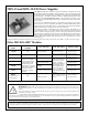
housing. Connections may be made to the MICRO-AMP via the optional
RS8 socket/wiring base, or the module may be mounted directly to a printed circuit
board (see page 3).
The small size and the slim ribbon-style connecting cable of SP100 Series sensors
make it possible to use photoelectrics in many situations previously thought to be
impractical or even impossible.
MICRO-AMP
®
System
MA3 and MA3P Modulated Ampliers
03340F3G
Model MA3P: PNP (current sourcing) output
Hookup Diagram, MA3P Amplier