PresencePLUS® P4 BCR/BCR 1.3 User's Manual Banner Engineering Corp. P/N 122800 rev.
Table of Contents 1. Product Support and Maintenance...................................................................7 1.1 Product Support......................................................................................................................7 1.2 Maintenance...........................................................................................................................8 2. System Description .........................................................................................
PresencePLUS® P4 BCR/BCR 1.3 7/2009 5.4.1 Flexible Inspection Loading........................................................................................40 5.4.2 Inspection Storage Capacity......................................................................................41 5.4.3 Opening an Inspection from the Sensor or a Library..................................................42 6. System Setup Window Overview....................................................................45 6.
7/2009 PresencePLUS® P4 BCR/BCR 1.3 7.4.6 Test Tool...................................................................................................................214 8. Communication Tool Setup...........................................................................235 8.1 Ethernet Connection...........................................................................................................235 8.2 Serial Connection..............................................................................
PresencePLUS® P4 BCR/BCR 1.3 7/2009 12.2 Three Pulse Set Overview................................................................................................277 12.2.1 Product Select in Three-Pulse Configuration.........................................................277 13. Saving Inspections.......................................................................................279 13.1 Saving Inspections to a Vision Sensor.............................................................................
1 Product Support and Maintenance This section provides general Banner resources and specific documentation for installers and operators of this PresencePLUS Vision Sensor. Attention: Not to be Used for Personal Protection. Never use these products as sensing devices for personel protection. Doing so could lead to serious injury or death. These sensors do NOT include the self-checking redundant circuitry necessary to allow their use in personnel safety applications.
Product Support and Maintenance 7/2009 2. Pack the sensor carefully. Damage which occurs during return shipping is not covered by warranty. Factory Support Call, e-mail, fax, or write your local Banner representative or a Banner Applications Engineer for support. Applications Engineers are available from 8:00 A.M. to 5:00 P.M. Central Time, Monday through Friday, excluding holidays. Phone Local: 763.544.3164 Toll Free: 1.888.3.SENSOR (1.888.373.6767) Fax 763.544.
2 System Description The PresencePLUS ProII and P4 sensor families are easy-to-use camera systems with advanced visual inspection capability. With minimal knowledge of vision systems, a user can quickly set up a PresencePLUS ProII or P4 and run an inspection that tests products accurately, rejecting bad products on a production line. Inspections are set up using a personal computer (PC).
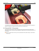
System Description 7/2009 In the application shown above, as each plastic formed part comes past the Vision sensor, an inspection is performed. If the part is not shaped correctly as shown here, the inspection fails. 2.1.2 PresencePLUS® P4 Components The PresencePLUS P4 system consists of the Sensor and a PC with PresencePLUS software and the appropriate connections. The Sensor requires lighting and a trigger device, and an optional video monitor can be connected.
7/2009 System Description 2.1.3 P4 Cable Connections Note: The sensor power must be 24V dc ± 10% if a light source is powered by the sensor. Crossover Ethernet Cable (to PC Ethernet Port)* Monitor Cable (to Video Monitor, optional) STPX07 — 2.1 m (7') BNC06 —2 m (6') STPX25 — 7.6 m (25') BNC15 — 5 m (15') or BNC30 — 9 m (30') Standard Ethernet Cable (to PC via Network Hub Serial Cable (to PC serial Port)* or Switch DB9P06 — 2 m (6') STP07 — 2.
System Description 7/2009 STP25 — 7.6 m (25') DB9P30 — 9 m (30') *The Sensor can be connected to the PC via a serial cable or an Ethernet network; Ethernet provides faster communication.
7/2009 System Description 2.2.1 Main Menu Toolbar Use the Main Menu toolbar to navigate between the Sensor options. Proceeding from left to right, the buttons in the Main Menu toolbar step through the process of creating and controlling an inspection. Each button is explained in the illustration below and in the table that follows. The following table describes the screen associated with each button in the Main Menu.
System Description 7/2009 Inspection-Specific Screens Help Call the Help window or the About window. 2.2.2 Image Window The Image window, on the left side of the screen, displays images acquired from the camera or the reference image that is set for the current inspection. The toolbar buttons in the Image window are explained below. Note: The reference image is used as a template for developing an inspection; it establishes the initial values for the Vision tools.
7/2009 System Description 2.2.3 Navigation/Results Window The Navigation/Results window, at the bottom of the screen, displays tool navigation buttons or inspection results files. Navigation Buttons Clicking on the Tools button in the Main Menu toolbar brings up the tool navigation buttons in the Navigation/Results window. When setting up or using tools, click on any tool navigation button to get the corresponding tab in the Configuration window.
System Description Icon 7/2009 Description Delete Selected Tool -- deletes the selected tool from the current inspection. Delete Selected Tools -- deletes the selected tool and all the tools to the right of the selected tool. Copy Selected Tool -- clones the selected tool. Expand Button Clicking on the Expand button ( ) toggles the size of the Navigation/Results window to accommodate an expanded list of inspection results files, as shown below. 16 Banner Engineering Corp. - Minneapolis, MN USA - www.
7/2009 System Description 2.2.4 Configuration Window The Configuration window, on the right side of the screen, displays the currently selected options with multiple tabs. Clicking the Setup, Tools, Teach, Run, System, Save, or Help buttons on the Main Menu toolbar changes the contents of the Configuration window accordingly. 2.2.5 Status Window The Status window, shown below, provides the following Sensor feedback.
System Description Region 7/2009 Description Image update completion -- progress bar shows relative image update completion when an image is being transferred from the camera to the PC (this flickers, and is next to Connection: Sensor 192.168.0.1). Current zoom value - works with the Zoom icon (magnifying glass). Current grayscale value -- the 0-255 gray scale value of the pixel under the cursor.
3 Getting Started This section begins with some Vision basics, then provides a brief overview of how to install the software, and the general steps to creating an inspection. 3.1 Installing the PresencePLUS Software The PresencePLUS software CD includes the sensor software and this documentation. 3.1.1 Installing the Software To install the PresencePLUS software: 1. Close all active programs. 2. Make sure that no previous installations of PresencePLUS are installed. 3.
Getting Started 7/2009 Note: The following instructions assume you are installing the software on Windows XP. 3. If using an Ethernet communication cable, configure the IP address as follows: a. Open Network Properties on the PC (right-click on the Network Neighborhood icon). 20 Banner Engineering Corp. - Minneapolis, MN USA - www.bannerengineering.com Tel: 763.544.
7/2009 Getting Started b. On the Local Area Connection, right-click on Properties. Note: The PC in the example above has a second network card which is used to connect to the camera so it is using Local Area Connection 2. c. In the dialog, click on Internet Protocol (TCP/IP) and click the Properties button. P/N 000000 Banner Engineering Corp. - Minneapolis, MN USA - www.bannerengineering.com Tel: 763.544.
Getting Started 7/2009 4. In the Internet Protocol (TCP/IP) Properties dialog, select Use the following IP address and make sure that the the IP address is 192.168.0.2, and the subnet mask is 255.255.255.0. 22 Banner Engineering Corp. - Minneapolis, MN USA - www.bannerengineering.com Tel: 763.544.
7/2009 Getting Started 5. Start the sofware. 6. Upon initial startup, the software communication is not configured, and the following error message is displayed. 7. Click Yes to open the Communication screen. 8. Establish communications as follows: Ethernet 1. When the software is started for the first time, the IP address is "Localhost." Connection Choose Ethernet (RJ 45). 2. Change the IP address to 192.168.0.1 (default IP address of the sensor). 3. Click OK. P/N 000000 Banner Engineering Corp.
Getting Started 7/2009 3.2 Typical Setup and Startup Sequence The following subsections proceed through a typical Sensor setup and startup sequence 1. 2. 3. 4. Connect and power up the hardware. Start up the software. Set up hardware parameters. Build and run an inspection. 3.3 Startup and Troubleshooting The following explains how to verify connections and start the PresencePLUS software. 1. Verify cable connections. • The sensor is connected to a PC with an Ethernet crossover cable ofr a serial cable.
7/2009 Getting Started • During powerup, all the sensor LEDs illuminate for 15 to 20 seconds. • After the Red Error LED turns OFF, verify that the Green power LED is flashing. 7. Launch the Software. • Click Start > PresencePLUS to start the program. • If the sensor has a different IP address than the default address (192.168.0.1), or if it is connected through a serial connection, the following error message will display: Sensor not found on specified IP address 192.168.0.1.
Getting Started 7/2009 Problem Cause/Solution • Error message "Failed to capture a full-resolution image. Please try again." • Image is frozen on PC, but image on monitor updates properly.Image is frozen on PC, but image on monitor updates properly. • Indicator lights on RJ-45 port are OFF. Ethernet connection lost. • Focus number does not update. • QuickStart fails. • Errors when saving inspections to the sensor. FTP communications is blocked. • Error code is displayed on PC.
7/2009 Getting Started 1. Setup screen: a. b. c. d. e. Set up the camera, lens, and lighting. Choose trigger option Continuous for a live image. Click Auto-exposure to adjust the image brightness. Focus the lens by turning the lens focusing ring until the focus value is maximized. When the desired image is shown, click Next to proceed to the Tools screen. 2. Tools screen: a. Add Location tool(s) to find the target to adjust the Regions of Interest (ROI) for translational and rotational changes. b.
Getting Started 7/2009 • To select an inspection (in the Select tab), enable Software Override, and select the inspection file from the list of stored inspections on the camera. • An alternate method is to use Hardware input to select an inspection via discrete inputs to the controller. 5. Begin inspection: To begin inspecting, click the Start button in the Run screen. 28 Banner Engineering Corp. - Minneapolis, MN USA - www.bannerengineering.com Tel: 763.544.
4 Setup 4.1 Setup Screen The Vision sensor has two modes: running and idle. If the sensor is idle when you start up the PresencePLUS software while your PC is connected, the software starts in the Setup screen. If the sensor is running, then the software starts in the Run screen. 4.2 Capturing a Reference Image The reference image is used as a template for developing an inspection. The Vision tools use this image to acquire the critical information needed for the inspection.
Setup 7/2009 4.3.1 Reference Image Source Before capturing an image, you need to determine what will trigger the Sensor to capture and image. The Sensor can be triggered to capture an image in one of the following ways. 30 Banner Engineering Corp. - Minneapolis, MN USA - www.bannerengineering.com Tel: 763.544.
7/2009 Setup Trigger Option Description Continuous The sensor will update continuously in Setup mode. External Images are acquired only in reponse to a signal from an external source as configured on the Trigger tab. Choose External if the part will be moving during the inspection to capture an image with the same conditions as the inspection conditions. Manual Images are acquired only then the Trigger button is clicked.
Setup 7/2009 Field Description • Running -- Auto exposure is currently running. • Finished -- Auto exposure has run and is complete. • Image too dark -- Auto exposure could not brighten the image enough. Add more light to the inspection, or increase the exposure manually. • Image too bright -- Auto exposure could not darken the image enough. Remove light to the inspection, or decrease the exposure manually.
7/2009 Setup 4.4.1 Trigger Settings Field Description Trigger Divide (range: 1-10,000 triggers) Sets the sequence of valid triggers. If set to 1, an image is captured in response to every valid trigger; if set to 2, and image is captured in response to every second valid trigger, and so on. Trigger Delay (range: 0-8,000 ms) Fixed time (ms) from the instant the Sensor receives a valid trigger to the instant the Sensor captures the image.
Setup 7/2009 4.4.2 Resolution Increases or decreases the resolution on the displayed image. A lower resolution will have a faster PC update. The resolution does not change the inspection. Resolution options are 1:1, 4:1, 16:1, and 64:1. 4.5 Advanced Tab The Advanced tab on the Setup screen allows you to adjust the field of view (FOV). The FOV is the image area at the focal plane of a camera. You can use the maximum FOV or adjust the FOV to improve performance.
7/2009 Setup Default Mode The Default Mode determines whether to use the Current FOV or Maximum FOV by default. Maximum and adjusted FOV The FOV is denoted by the green box surrounding the image in the Setup screen. The maximum FOV is shown below. To improve performance, reduce the size of the FOV either vertically, horizontally, or both, as shown below. P/N 000000 Banner Engineering Corp. - Minneapolis, MN USA - www.bannerengineering.com Tel: 763.544.
Setup 36 7/2009 Banner Engineering Corp. - Minneapolis, MN USA - www.bannerengineering.com Tel: 763.544.
5 Tools Screen 5.1 Overview Using the Tools screen, the user establishes the inspections that the Sensor will execute. Three sources of inspections are available: 1. Building an inspection from scratch is the typical method of establishing an inspection. The Tools screen is designed to aid the user in building an inspection. A typical inspection consists of Location Tools, followed by Vision Tools, Analysis Tools, and finally (if required) the Communication Tool.
Tools Screen 7/2009 5.2 Typical Build/Modify Procedure 5.2.1 Choosing a Tool To choose the right tools for an inspection, consider the tool's parameters and result options: • Parameters are selected inputs for each tool (for example, relative threshold). • Results are the information returned from the tool after it has executed. Some tools perform evaluations, while others provide positional data for the tools that follow.
7/2009 Tools Screen • The button in the Navigation/Results window that appears will show the first nine characters after exiting the tool. 5.2.5 Removing a Tool To remove a tool: 1. Choose the tool to be removed in the Navigation/Results window. 2. Click the Delete button in the lower-left corner of the screen. 5.3 Quick Teach Quick Teach provides the fastest and easiest method of establishing an inspection. Quick Teach will use the reference image to establish Pass/Fail parameters of the Test tools.
Tools Screen 7/2009 5.4.1 Flexible Inspection Loading Release 2009R1B introduces a more flexible inspection loading capability that allows most inspections created by any PresencePLUS vision sensor to be loaded through the PresencePLUS software even if connected to a different type of PresencePLUS vision sensor. This means that you can now load, for example, an inspection created by an OMNI 1.3 into PresencePLUS software connected to a standard OMNI.
7/2009 Tools Screen Inspection Source Inspection Destination Result Possible Inspection Modifications Color sensor (for Standard grayscale A dialog indicates that the None required example, a Color sensor (for example, a image color has changed and OMNI) standard OMNI) the inspection loads Grayscale sensor Color sensor (for (for example, a example, a Color standard OMNI) OMNI) A dialog indicates that the None required image color has changed and the inspection loads High Resolution (1.
Tools Screen 7/2009 Sensor Type INS Storage Memory Number of INS Files Number of INS files without Reference Images* Pro II Color 64MB 160 999 Area/GEO/Edge 8MB 150 500+ OMNI 32MB 85 999 OMNI Color 32MB 72 999 Pro II 1.3 64MB 44 999 OMNI 1.3 64MB 44 999 BCR 8 400+ GEO/Edge/Area/BCR 1.3 32 20 999 *Not saving a reference image with the inspection frees up a lot of room onboard the sensor.
7/2009 P/N 000000 Tools Screen Banner Engineering Corp. - Minneapolis, MN USA - www.bannerengineering.com Tel: 763.544.
6 System Setup Window Overview To access the System Setup window, click the System button in the Main Menu toolbar on the applcation window. To clear changes, click Cancel. To save changes and exit the System Setup window, click OK. To exit the System Setup window without changes, click the X in the upper-right corner of the window. Note: To make changes to the sensor selections, an inspection must not be running. To stop a running inspection, click the Stop button in the Run tab.
System Setup Window Overview 7/2009 6.1 Sensor Select Tab Use the Sensor Select tab to establish the Sensor connection with the PC. Note: An option box to open the Sensor Select tab is automatically displayed if the Sensor either is not connected or is connected but with the wrong IP Address selected. Sensor Neighborhood Fields The Sensor Neighborhood will list sensors in your environment. The following describes the fields in the Sensor Neighborhood. 46 Banner Engineering Corp.
7/2009 System Setup Window Overview Field Description Available If the Icon is green (Yes), the sensor is available; if yellow, a connection can't be established for some reason; if red (No), the sensor is not available. Note: The sensor to which you are currently connected will sho up as unavailable (red icon). Name The name of the sensor. IP Address The IP address assigned to the sensor. Product ID The sensor model and type. Sensor Version The sensor version.
System Setup Window Overview 7/2009 6.1.1 Change Sensor IP Address To change a sensor's IP address: 1. Select the sensor in the Sensor Neighborhood 2. Click the Change Sensor IP Address button. 48 Banner Engineering Corp. - Minneapolis, MN USA - www.bannerengineering.com Tel: 763.544.
7/2009 System Setup Window Overview 3. Click Next 4. Enter an appropriate sensor name in the New Sensor Name field. 5. Click Finish. 6.1.2 PC (GUI) to Sensor Connection Setup Use this field to select whether the Sensor will communicate via the Ethernet port or a serial connection. P/N 000000 Banner Engineering Corp. - Minneapolis, MN USA - www.bannerengineering.com Tel: 763.544.
System Setup Window Overview 7/2009 • If you select Ethernet (RJ 45), the Connection IP Address shows the IP address for which the software is looking. Initially, the IP address should be 192.168.0.1, the default IP address of the sensor. • If you select Serial, the IP address is not applicable. 6.1.3 IP Address History Use this button to view previous IP Addresses and Subnet Masks. 50 Banner Engineering Corp. - Minneapolis, MN USA - www.bannerengineering.com Tel: 763.544.
7/2009 System Setup Window Overview 6.2 Communication Tab The Communication tab is used to configure: • General Communication Setup • Remote Command Configuration (RCC) Communication Tab P/N 000000 Banner Engineering Corp. - Minneapolis, MN USA - www.bannerengineering.com Tel: 763.544.
System Setup Window Overview 7/2009 6.2.1 Communication Setup Banner Vision sensors support the following communication options: • Ethernet Sockets 1-10 • Serial 1 • Industrial Ethernet Ethernet Connection In order to establish an Ethernet connection , the external device must be directed to the correct IP address and the correct TCP port. In TCP/IP protocol, a TCP port number is used with the IP address to identify a specific path or socket.
7/2009 System Setup Window Overview Valid user TCP/IP port numbers are in the range of 1024 through 65535. The PresencePLUS GUI provides automatic notification if you attempt to use a reserved port. To view an Ethernet connection: 1. Click on the System button in the Main Menu toolbar to bring up the System Setup window. 2. Click on the Communication tab. 3. Choose a connection from the fixed Connection drop-down list of the Communication Tool Setup field.
System Setup Window Overview 7/2009 Socket Default IP Address Port 7 192.168.0.1 20006 8 192.168.0.1 20007 9 192.168.0.1 20008 10 192.168.0.1 20009 Serial Connection The sensor has a single serial connection that you can configure, Serial 1: • Serial 1 is the DB-9 connector. Note: The Pro has 2 serial connections. Serial 2 in the dropdown list is to support those sensors. The sensor has one serial connection that can be configured: Serial 1 is pins 1, 9, and 10.
7/2009 System Setup Window Overview Note: Because there is no flow control for the serial connections, the sensor wil not detect or log a lost or broken connection Industrial Ethernet Protocol Protocol selects which Industrial Ethernet protocol is being used. This changes the string format and the word/register values reported in the PLC Map.
System Setup Window Overview 7/2009 • ControlLogix packing format is used to store characters into registers when the Character String Order option is set to “Low Byte – High Byte” selection. Please note that in this particular case, the length of the string is still stored in one 16-bit register, and only the order of characters in each 16-bit register follows the ControlLogix format: 6.2.
7/2009 System Setup Window Overview ACTION is an operation the user intends to perform on the OBJECT_IDENTIFIER. There are three possible actions available: • GET — used to retrieve information associated with the named object. This information can be a Boolean value, and unsigned or signed number, a string or, for complex objects like the Communications tool, a field-delimited record that includes other data types. • SET — used to assign a value to a named object.
System Setup Window Overview System Object, Component, or Activity Object or Activity Identifier 7/2009 Support Actions Required Qualifiers Optional Qualifiers Comments immediately, and the command will block until a default 30-second timeout expires. If TRIGGER NOWAIT is specified, remote teach will occur immediately, and the command will return right away. If a timeout value is specified, the command will block until the specified timeout expires.
7/2009 System Setup Window Overview System Object, Component, or Activity Object or Activity Identifier Support Actions Required Qualifiers Optional Qualifiers Comments (1,2,..,n) or by specifying its name. By default, data for the first comm tool will be retrieved.
System Setup Window Overview 7/2009 System Object, Component, or Activity Object or Activity Identifier Support Actions Exposure EXPOSURE Exposure Required Qualifiers Optional Qualifiers Comments GET None Retrieve the camera exposure EXPOSURE SET Positive Number None Get the camera exposure Frame Number FRAMETAG Tag SET ENABLE None Enables frame number as command acceptance indicator Frame Number FRAMETAG Tag SET DISABLE None Disables frame number as command acceptance indicator
7/2009 System Setup Window Overview Syntax Description set stringtool tool_name|tool_number operand_1|operand_2 Sets the specified tool operand, if it is a constant. Value should be a quoted string (see Character Strings 6.2.2.6.1 Character Strings on page 248). get stringtool tool_name|tool_number operand_1|operand_2 Gets the value of the specified tool operand, if it is a constant.
System Setup Window Overview 7/2009 • -306 – Requested comm tool is not configured for RCC • -307 - Tool executed with an error or did not execute • -308 - Specified tool operand is not a constant, and cannot be modified • Reset command error codes • -401 – Reset command attempted in the middle of the inspection • -402 – Reset command attempted in the middle of the product change • -500 – RCC commands are not accepted because the sensor is in the Playback mode • Timeout error codes • -600 – Product change
7/2009 System Setup Window Overview • Inspection is Executing and is Ready 4. SET GAIN or SET EXPOSURE commands can be successfully accepted under the following conditions: • Inspection is Executing and is Ready 5. GET status, counter or flag commands can be accepted at any time. If issued when inspection is Executing but is not Ready, these values may change as the inspection is executing. 6. GET COMMTOOL command can be successfully accepted if the inspection has been loaded.
System Setup Window Overview 7/2009 0000000118.116 CMD exec trigger 0000000118.483 OUT 0\x0D\x0A In this example, command exec trigger was sent to RCC interface. The interface was configured to use no start frame delimiter, and carriage return (\x0D) and line feed (\x0A) as frame delimiters. As soon as valid frame delimiters were received, the command exec trigger was sent for processing, and the command response was sent back after inspection finished executing.
7/2009 System Setup Window Overview • Any double quote encountered in the Barcode or String Tool will be converted to its ASCII Hex equivalent, “\x22”. For RCC input strings, the formatting rules are expanded to accommodate readability as follows: • Carriage return can be specified as character sequence "\r" (backslash-r). • Line feed can be specified as character sequence "\n" (backslash-n). • Double quote can be specified as character sequence "\"" (backslash-doublequote).
System Setup Window Overview Main Steps 7/2009 Tasks to Complete • Determines pass/fail condition of the inspection. • Gets the X, Y, and Rotation about Z-axis offsets. • Closes the connection to the RCC. 2. Run program. Note: The IP address and port number within the sample AS Language program must be modified to match the IP address and port number of the PresencePLUS sensor.
7/2009 System Setup Window Overview Establishing Sensor/Robot Communication Step 1 Main Tasks to Complete Install and connect 1. Install Banner PresencePLUS Vision Sensor version 2009R1B or later. a PresencePLUS 2.
System Setup Window Overview Step 2 7/2009 Main Tasks to Complete performed from the System Setup Dialog, Communications tab The default Ethernet port assignments are from 20000 to 20009. Note: Valid user TCP/IP port numbers for PresencePLUS sensors are in the range of 1024 through 65535. The PresencePLUS GUI will provide automatic notification if an attempt to use a reserved port is made. Any changes to the port assignment must be reflected in the AS Language program included in this document .
7/2009 System Setup Window Overview Step 3 Main Tasks to Complete 2. Click the OK button to accept the configuration. Kawasaki Protocol Defaults The default Kawasaki protocol configuration parameters are: • Ethernet Socket 1 configured for TCP/IP Port 20000 as the communications channel • No Frame Start (Command Start) delimiter • Carriage Return/Line Feed as Frame End (Command End) delimiter • Space as the input command field separator • Comma as the output field separator.
System Setup Window Overview Step 1 7/2009 Main Tasks to Complete the Tool Configuration 2. Select the Tools Configuration tab. dialog. 3. Scroll down to the Coordinate Tool, and then select the checkbox next to it, as shown below. 4. Click the OK button to close the Tool Configuration dialog. Step 2 Main Tasks to Complete Create a New Inspection using Setup. 70 1. In the PresencePLUS GUI, create a new inspection by pressing the Setup button in the upper-left corner of the GUI. 2.
7/2009 System Setup Window Overview Step 3 Main Tasks to Complete the part within the field-of-view. 2. Click the Geomtric Find button. 3. Draw the tool ROI (Region of Interest) to select the image feature of interest as shown below. 4. Click the Apply button to accept the ROI. 5. Click the Next button to return to the Tools menu. P/N 000000 Banner Engineering Corp. - Minneapolis, MN USA - www.bannerengineering.com Tel: 763.544.
System Setup Window Overview 7/2009 Step 4 Main Tasks to Complete Add a Coordinate tool to provide locational data for the Robot. 1. In the PresencePLUS GUI, click the Analysis Tools tab. 2. Click the Coordinate tool button to create a Coordinate tool. 3. Select Offset Only from the Tool List Filter drop-down menu. 4. Click the Next button to return to the Tools menu. Note: The X, Y and Rotation selections will default to GF_1. 72 Banner Engineering Corp. - Minneapolis, MN USA - www.
7/2009 System Setup Window Overview Step 5 Main Tasks to Complete Add a Test tool to receive a positive confirmation that the inspection ran successfully; that is, the part was found. 1. In the PresencePLUS GUI, click the Analysis Tools tab. 2. Click the Test tool button. 3. Select Coordinate Tool (COORD_1) from the Input 1 drop-down list. 4. Click on the Coordinate Tool (COORD_1) tab and make sure that the checkmark next to the X-Coordinate value checked.
System Setup Window Overview Step 5 7/2009 Main Tasks to Complete 6. Click the Back button. 7. Cleck the Next button to exit the Test Tool configuration. Step 6 Main Tasks to Complete Save and Start Inspection In the PresencePLUS GUI, click the Go To Run button. When prompted to save the inspection: 1. Enter a name in the Inspection Name field. 2. Click on the Save button. 3. Once the inspection is saved, click the Start button to start the inspection. 74 Banner Engineering Corp.
7/2009 System Setup Window Overview Kawasaki AS Language Sample This sample AS Language code snippet will assist with the integration of a Banner PresencePLUS Vision Sensor and a Kawasaki C/D/D+ Series Robot Controller.
System Setup Window Overview 7/2009 CALL tcp_open(.ret_val, 20000) IF .ret_val < 0 THEN PRINT "Unable to connect to RCC" RETURN END ; ; Trigger the camera and wait for the inspection to complete ; ; Send Trigger to camera and wait for the inspection to complete .$cmd_str = "EXEC TRIGGER"+$cmd_del CALL tcp_send(.ret_val, .$cmd_str) IF .ret_val < 0 GOTO tcp_error ; Read command response from camera .$rcv_str = "" CALL tcp_recv(.ret_val, .$rcv_str) IF .
7/2009 System Setup Window Overview ; ; Obtain the X, Y, and Rz offset data ; ; Send command to camera to acquire the Communication Tool ; result data .$cmd_str = "GET COORDTOOL"+$cmd_del CALL tcp_send(.ret_val,.$cmd_str) IF .ret_val < 0 GOTO tcp_error ; Read command response from camera .$rcv_str = "" CALL tcp_recv(.ret_val, .$rcv_str) IF .ret_val < 0 GOTO tcp_error ; Decode command response .$rsp_str = $DECODE(.$rcv_str, $cmd_del, 0) .ret_val = VAL(.$rsp_str) IF .
System Setup Window Overview 7/2009 ; TCP error tcp_error: PRINT "Error during send or receive via TCP:", .ret_val GOTO all_done ; RCC Command error cmd_error: PRINT "Error during command to camera:", .ret_val GOTO all_done ; Done with program all_done: CALL tcp_close .END ; ; Open a TCP connection to the RCC using specified TCP port number ; .PROGRAM tcp_open(.ret_val, .port) .ret_val = 0 .
7/2009 System Setup Window Overview connect_error: RETURN .END ; ; Close the TCP connection ; .PROGRAM tcp_close() .ret_val = 0 ; Initialize the return value TCP_CLOSE .ret_val, tcp_sock_id ; Check for errors IF (.ret_val < 0) THEN PRINT "Unable to close TCP connection, error id = ", .ret_val ELSE PRINT "TCP Connection has been closed" END .END ; ; Receive data over TCP connection ; .PROGRAM tcp_recv(.ret_val, .$receive) .ret_val = 0 ; Initialize the return value .
System Setup Window Overview 7/2009 ELSE PRINT "Received string too long" .ret_val = -1 END ELSE PRINT "Invalid number of elements received" .ret_val = -1 END END .END ; ; Send data over the TCP connection ; .PROGRAM tcp_send(.ret_val, .$data) .ret_val = 0 .$send_buf[1] = .$data .buf_num = 1 .send_timeout = 60 .error_return = 0 ; ; ; ; ; Initialize function return code Data to send Number of array elements send timeout send error return code TCP_SEND .error_return, tcp_sock_id, .$send_buf[1], .
7/2009 System Setup Window Overview 6.2.4 Using Custom_ASCII to Communicate with an External Device Over Ethernet To select Custom_ASCII, click on the RCC Protocol pull-down menu, and select Custom_ASCII from the menu. The protocol configuration for Custom_ASCII is displayed as shown below.
System Setup Window Overview 7/2009 6.3 P4 Input/Output Tab Use this tab to set t he functionality of the four programmable I/O connections. Inputs and Outputs I/O, Pin #, Function You can select Trigger, Product Change, Remote Teach, and Discrete inputs and outputs as eith NPN (current sourcing) or PNP (current sinking). Once NPN or PNP is selected, all inputs and outpus are either NPN or PNP. I/O 1 through 4 in the I/O column correspond to Pins 5 through 8 in the Pin # column.
7/2009 System Setup Window Overview ON OFF ON Trigger Output OFF Processing Time Delay Output Duration Latched Input/Ouput Tab P4 Input/Output Tab P/N 000000 Banner Engineering Corp. - Minneapolis, MN USA - www.bannerengineering.com Tel: 763.544.
System Setup Window Overview 7/2009 6.4 Strobe Tab Use the Strobe tab to set the strobe signal for a strobed light source. The strobe signal is a +5V dc TTL signal. Fields in the System Setup window's Strobe tab are described below: Strobe Tab 6.4.1 Strobe Width 84 Banner Engineering Corp. - Minneapolis, MN USA - www.bannerengineering.com Tel: 763.544.
7/2009 System Setup Window Overview Strobe Width Option Description Off The strobe output never becomes active (light off). On The strobe output remains active (light on). Exposure Duration The strobe output is active only while the sensor is acquiring an image. This is the default. Time Duration Sets the duration for active strobe output from the initial valid trigger (minimum pulse width has been satisfied) to the end of the duration. The range is from 0 to 4,000 ms. 6.4.
System Setup Window Overview 7/2009 6.6 Reset Tab Use the Reset tab to read sensor error codes, clear system errors and reestablish Sensor communications. 86 Option Description Reset Error Flag Click to clear the sensor's Red Error LED. Reset Error Log Click to clear the error log. System Reset Click to reboot the Sensor. (This is a system reboot and will take several seconds). Banner Engineering Corp. - Minneapolis, MN USA - www.bannerengineering.com Tel: 763.544.
7/2009 System Setup Window Overview Option Description Get Error Log Click to display the System Log icon in the Navigation/Results window. The System Log records information about all system failures (such as communication errors between the PC and the Sensor). Reset Tab 6.7 Start-Up Inspection Tab The options on the Start-Up Inspection tab: P/N 000000 Banner Engineering Corp. - Minneapolis, MN USA - www.bannerengineering.com Tel: 763.544.
System Setup Window Overview 7/2009 • Click on Setup Mode if you want the camera to start in Setup Mode after it is powered down. • Click on Inspection Name, and select an inspection from the drop-down list to have the sensor start up to run. Start-Up Inspection Tab P4 Start-Up Inspection Tab ProII Start-Up Inspection Tab 88 Banner Engineering Corp. - Minneapolis, MN USA - www.bannerengineering.com Tel: 763.544.
7/2009 System Setup Window Overview 6.8 NTSC Tab The Zoom Level adjustment on the NTSC tab is availalble only for single function, low-resolution sensors such as the Area and Geo. From the drop-down list, select the desired zoom level as it will appear on the optional NTSC video monitor that you can attach to the sensor. The default is 4:1. NTSC Tab P/N 000000 Banner Engineering Corp. - Minneapolis, MN USA - www.bannerengineering.com Tel: 763.544.
System Setup Window Overview 7/2009 6.9 Language Tab In the Languages tab, click on the down arrow for a drop-down list of the languages installed from the PresencePLUS software CD. Click on the desired language, then click Apply. At the next start-up, the PresencePLUS software will use the selected language. To save changes and exit the System Setup window, click OK. To exit the System Setup window without making any changes, click the X in the upper-right hand corner of the window.
7/2009 System Setup Window Overview 6.10 Tools Configuration Tool Configuration provides the ability to customize the Tools page within the PresencePLUS software. Entire tools, or their enhanced features, can optionally be displayed or hidden. This provides the ability to configure the system to better support your application, thus further simplifying the creation and modification of inspections. To assist with the customization, the list of tools for the connected sensor is displayed in a tree view.
System Setup Window Overview 7/2009 6.10.1 Standard Mode Choose this option to reset all tool configuration settings for the connected sensor to the factory defaults. 6.10.2 Enhanced Mode Choose this option to enable all tools and all tool's enhanced features for the connected sensor. 6.10.3 Custom Mode Choose this mode to customize the tools configuration settings within the tree view. This mode is automatically selected when changes are made to the tree view.
7/2009 System Setup Window Overview - Select the tool to activate - Enter the license key received for the sensor - Click on the 'Register' button To view licenses currently registered within the sensor, click the 'Help' button on the title bar and select 'About' from the menu. The licenses are also displayed next to the product name in the title bar. P/N 000000 Banner Engineering Corp. - Minneapolis, MN USA - www.bannerengineering.com Tel: 763.544.
7 PresencePLUS Software Tools 7.1 ROI Types ROI types include Area, Search, and Linear. 7.1.1 Linear ROI Linear ROIs are used by tools that scan along a defined line in a defined direction. Data are averaged along a linear ROI wider than 1 pixel to provide accurate test results. You can adjust the ROI width in increments of 4; that is, 1, 5, 9, 13, and so on. The ROI is widened symmetrically. Note: Widening an ROI provides an average value/location, which results in improved repeatability. 7.1.
PresencePLUS Software Tools 7/2009 7.1.3 Search ROI Geometric Find, Geometric Count, Pattern Find, and Pattern Count ROIs, like Area ROIs, can be rectangular, elliptical, or circular; however, these ROIs are also bounded by a Search ROI. The Search ROI is indicated by a yellow box that is always rectanagular and, by default, is 20% to 30% larger than the Area ROI, which is red. 7.2 Location Tools 7.2.1 Locate Tool The Locate tool locates the position of a target in a field of view.
7/2009 PresencePLUS Software Tools Adding a Locate Tool To add a Locate tool to an inspection: 1. Click the button of the tool to be added to the inspection. 2. If desired, rename the tool. 3. Draw an ROI. Field/Button Description Use this field to rename the tool. The default is tool_name_1, tool_name_2, and so on, where the default tool_name depends on the tool being created (for example, locate, edge or the like). The name can have only alphanumeric characters and underscores with no spaces.
PresencePLUS Software Tools 7/2009 Threshold Type The threshold is used to mark the gray scale transition point. The tool marks the edge when the pixel intensity crosses the threshold level. From the dropdown list, select one of the following: • Relative • Absolute • Edge Strength Relative Threshold Relative threshold is the default, and it finds an edge at a relative pixel intensity. The brightest gray scale level is 100% and the darkest is 0%.
7/2009 PresencePLUS Software Tools Field/Graph Description Value Value is displayed when Type is Absolute. Enter a specific gray scale value from 0 to 255. Polarity • Bright to Dark finds edges that start above the threshold value and cross below the threshold value. • Dark to Bright finds edges that start below the threshold value and cross above the threshold value. • Bright or Dark finds any edge.
PresencePLUS Software Tools Field 7/2009 Description • Bright or Dark finds any edge. Graph Tab When Edge Strength is selected in the Input tab, the software displays the Graph tab. This tab provides similar information to the Input tab, but displays separate Edge Profile and Edge Strength graphs for easier viewing. The Edge Profile graph represents the absolute gray scale level across the tool ROI. The Edge Strength graph represents the change in gray scale along the tool ROI.
7/2009 PresencePLUS Software Tools Field Description ROI Width Increases in increments of 4 pixels (for example, 1, 5, 9, 13, ...) up to the total FOV size. Some things to note: • Narrow ROIs execute faster but could miss the edge. • Wide ROIs are more consistent but don't execute as fast. • The ROI must be 13 pixels or wider to calculate the rotation of a part. Smoothing Runs a rolling average along the ROI length. It filters out sharp changes in the edge profile.
PresencePLUS Software Tools 7/2009 Note: ROI width must be 13 pixels or greater. Advanced Tab If you have enabled the Advanced Configuration in the System setup, the software displays and Advanced tab. This enables you to force any location tool to Absolute Positioning. Graph Tab When Edge Strength is selected, the Graph tab appears on the tool window. The graph for the Input tab overlays both the edge strength graph and the edge profile.
7/2009 PresencePLUS Software Tools 7.3 Premium Vision Tools Premium Vision tools are advanced tools for specialty applications. These include Barcode, Bead, Optical Character Recognition (OCR) and Optical Character Verification (OCV) tools. P/N 000000 Banner Engineering Corp. - Minneapolis, MN USA - www.bannerengineering.com Tel: 763.544.
PresencePLUS Software Tools 7/2009 7.3.1 Barcode Tool The Barcode tool is more of an appliance than a generic vision tool. The tool is easy to use: push one button and it just works. In addition to decoding the data present in the barcode symbol, the Barcode tool also grades the symbol according to ISO-specified quality parameters. These grades are meant to test whether the physical barcode symbol was printed correctly.
7/2009 PresencePLUS Software Tools Barcode Type P/N 000000 Banner Engineering Corp. - Minneapolis, MN USA - www.bannerengineering.com Tel: 763.544.
PresencePLUS Software Tools 7/2009 Select one of the following for the Barcode Type: • Any -- Enables the Barcode tool to read any supported barcode type • DataMatrix • DataMatrix (Dot Peened) • Linear Code 128 • Linear Code 39 • Linear Code CODABAR • Linear Code 2 of 5 Interleaved • Linear Code EAN 13 • Linear Code EAN8 • Linear Code UPCE • Linear Code POSTNET • Linear Code IMB • PDF-417 • Linear Code PHARMACODE • MULTIPLE -- When you select this option, you can select multiple barcode types you want th
7/2009 PresencePLUS Software Tools The Results field provides the number of barcodes found, barcode type, data read, and quality parameters. Note: When the Barcode tool finds multiple barcodes, the Select Barcode field allows you to select each barcode individually. The multiple barcodes are arranged in order (with respect to image origin) from left to right, top to bottom, according to the location of the lower-left corner of the barcode. 7.3.
PresencePLUS Software Tools 7/2009 All Barcodes Options 108 Banner Engineering Corp. - Minneapolis, MN USA - www.bannerengineering.com Tel: 763.544.
7/2009 PresencePLUS Software Tools Color Scheme The Color Scheme determines what color scheme of barcode the sensor will reconize. Of the three Color Scheme options, the default is Either. Color Scheme Option Description Black on White The sensor will recognize barcodes that are black (or dark) marked on a white (or light) background. White on Black The sensor will recognize barcodes that are white (or light) marked on a black (or dark) background.
PresencePLUS Software Tools 7/2009 The Decoder Mode determines which decode algorithm to employ and how imperfections in barcode images are handled. Of the two options, Robust is preferred and is the default. Decoder Mode Option Description Robust When you select Robust, the sensor employs an algorithm that performs routines to correct for imperfections of the barcode image. This mode typically has the higher read rate.
7/2009 PresencePLUS Software Tools 7.3.3 Barcodes Read by Banner BCR Barcode Codabar (NW-7 in Japan, USD4, 2 of 7) (Code 25, ITF-14, ITF, “I” 2 of 5, I25) Date Format Industries Notes 1972 linear 16-characters, self-checking, variable length, discrete, start/stop characters.
PresencePLUS Software Tools Barcode Date 7/2009 Format Industries Notes Example single digit country (or product type) code. UPC-E ~1976 linear small retail products in USA and Canada (point-of-sale) 6 characters (numeric only), check sum, continuous. Commonly called a “zerosuppressed” version of the standard UPC-A symbol, this barcode is used on small items or crowded labels where space is at a premium.
7/2009 PresencePLUS Software Tools Barcode Date Format Industries Notes Example strings are stored in Postnet codes: a 5 digit ZIP code (with check digit), a 9 digit ZIP+4 code (with check digit), and an 11 digit ZIP+4 plus delivery code (with check digit). Data Matrix (ECC 200) 1990 PDF417 IMB P/N 000000 2006 2D Integrated circuit, printed circuit boards and automotive, aerospace, electronics,semiconductor and medical device industries. Stores up to 3116 numbers or 2335 ASCII characters.
PresencePLUS Software Tools Barcode Date 7/2009 Format Industries Notes Example the United States Pharmacode linear Parmaceutical Binary Code and is used for packing control in the pharmaceutical industry. Pharmacode can represent only a single integer from 3 to 131070. 7.3.4 Bead Tool The Bead tool is used to inspect parts on which an application of adhesives or sealant material has been placed. In an industrial setting, this "bead" of material is commonly applied in a strip on a known path.
7/2009 PresencePLUS Software Tools ProII Color ProII/ProII 1.3 OMNI Color OMNI/OMNI AREA/AREA1.3 EDGE/EDGE GEO/GEO 1.3 1.3 1.3 BCR/BCR 1.3 Yes Yes No Yes Yes No No No Bead Tool Input Tab Drawing a Connected Line ROI To begin defining the ROI: P/N 000000 Banner Engineering Corp. - Minneapolis, MN USA - www.bannerengineering.com Tel: 763.544.
PresencePLUS Software Tools 7/2009 1. Click on the Draw ROI button. 2. Click on the bead to mark a starting point. A small circle will mark this start point. As you move the mouse away from the start point, the software draws a dotted line following the mouse pointer. 3. Click on any part of the field of view, and a second point is drawn with a line connecting the two dots to define a line segment. 4. Add more segments as necessary.
7/2009 PresencePLUS Software Tools Modifying an ROI To change the position of a point, select the point and drag with the cursor. You can add more points to the line by clicking on the line connecting different points. To extend the ROI to more line segments, click the Extend button, and select from the beginning or the end of the existing ROI. To delete a point on the ROI, select the point, and click the Delete button. You can also change the ROI width: • By changing the value in the ROI Width field.
PresencePLUS Software Tools 7/2009 One-Shot Once an ROI has been defined and terminated, the software performs a one-shot analysis of the existing image. The software sends the values of all the input parameters to the sensor where the sensor performs analysis on the reference image with those values, and computes initial values for number of good, narrow, and wide regions as well as other characteristics of the regions.
7/2009 PresencePLUS Software Tools Adaptive thresholding is a technique that is used to adjust the threshold for the BLOB tool based upon lighting changes and image content within the ROI. It performs best if used with bi-modal images, which have a clear contrast in the ROI.
PresencePLUS Software Tools Samples Per Pixel Bead Width 7/2009 From the drop-down list select the pixels to sample: Every Pixel, nd th Every 2 Pixel or Every 4 Pixel. Change the value for Min and Max Bead Width by using the arrow keys in each field, or by typing the desired value. Ignore Boundary Pixels Check this box if you want the software to ignore boundary pixels. Boundary pixels are bead pixels that touch the ROI. If you choose to ignore boundary pixels, you might ignore one or more segments.
7/2009 PresencePLUS Software Tools Result Example Value Threshold used 137 Minimum width found 8.20 (px) Maximum width found 19.91 (px) Average width found 12.58 (px) Number of good regions 8 Total length of good regions 175.00 (px) Longest good region length 53.00 (px) Number of narrow regions 5 Total length of narrow regions 72.00 (px) Longest narrow region length 20.00 (px) Number of wide regions 3 Total length of wide regions 87.00 (px) Longest wide region length 40.
PresencePLUS Software Tools 7/2009 • Should I Use OCR or OCV?7.3.8.1 Should I Use OCR or OCV? on page 142 • Decoded String Field7.3.5.1 Decoded String Field on page 143 • Trainer7.3.6 Trainer on page 143 Supported Platforms ProII Color ProII/ProII 1.3 OMNI Color OMNI/OMNI AREA/AREA1.3 EDGE/EDGE GEO/GEO 1.3 1.3 1.3 BCR/BCR 1.
7/2009 PresencePLUS Software Tools Note: The software ignores spaces. Note: For OCV, if the Decoded string does not match the Expected String, then the Decoded string will be displayed in red. 7.3.6 Trainer The Box Tab When you capture a reference image using the OCR or OCV tool, these tools use sophisticated pattern recognition algorithms to box what is estimated to be individual characters in a captured image.
PresencePLUS Software Tools 7/2009 On the Box tab, you can calibrate the following: • Image Control Parameters7.3.6.1.2 Image Control Parameters on page 145 • ROI Control Calibration7.3.6.1.3 ROI Control Calibration on page 146 • Character Settings Calibration7.3.6.1.4 Character Settings Calibration on page 147 • Character Connectivity Calibration7.3.6.1.5 Character Connectivity Calibration on page 152 • Thresholding Calibration7.3.6.1.
7/2009 PresencePLUS Software Tools Button Description Use the right arrow to cycle down through a list of images, and use the left arrow to cycle up through the list. Click this button to add the currently displayed image to the Training List. Note: Use this button as Sensor images are being captured. Click this button to remove the currently selected image from the Training List. Click this button to import images from the player/recorder folder where bitmaps are saved.
PresencePLUS Software Tools 7/2009 Parameters The following describe the image control parameters set in this group. Image Description Reference Image Boxing is first done using the Reference Image captured with the OCR or OCV tool. Training List Create or use a Training List (or Play List) of images previously saved, or by adding images currently displayed in the Image window to get some variants of character patterns.
7/2009 PresencePLUS Software Tools ROI Control Description Rotation Use the up or down arrow controls to rotate the ROI clockwise, or counterclockwise so that the ROI aligns with the character string image. Deslant Angle In order for the OCV/OCR Vision tool to box correctly, there must be a minimum of a 2 to 3 pixel-wide column between characters.
PresencePLUS Software Tools Standard Character Settings 7/2009 Enhanced Character Settings Parameters The following are parameters to used to calibrate character settings. 128 Character Settings Description Print Contrast From the drop-down list, select Dark on bright or Bright on dark, which defines the relationship of the characters and the background; that is black on white or white on black.
7/2009 PresencePLUS Software Tools Character Settings Description Min Stroke Thickness Use the up and down arrow controls to specify the stroke thickness of the characters. This is used to eliminate spurious marks that might result in false-positive identification of characters. Additional Information Enhanced Character Settings The enhanced OCR/OCV settings provide for fine-tuning how the sensor boxes characters. To enable Enhanced OCR/OCV tools: 1.
PresencePLUS Software Tools Enhanced Character Settings Description Min Box Width These values determine the minimum width and height allowed for the boxing around a character. Typically, these values will be the width (and height) of the smallest valid character.
7/2009 PresencePLUS Software Tools Enhanced Character Settings Description Max Box Width These values determine the maximum width and height allowed for the boxing around a character. Typically, these values will be the width (and height) of the largest valid character.
PresencePLUS Software Tools 7/2009 Character Connectivity Calibration Intra-Character Connectivity defines the maximum number of pixel spaces between two character strokes so that both strokes will be considered part of the same character. In the example below, if the Horizontal Gap were defined too small, the "H" could be considered an I - I.
7/2009 PresencePLUS Software Tools Intra-Character Connectivity Description Additional Information number of pixel spaces that can exist between two horizontal character strokes so that the image is boxed as a single character image. Max Vertical Gap Use the up or down arrow controls to set the maximum number of pixel spaces that can exist between two vertical character strokes so that the image is boxed as a single character image.
PresencePLUS Software Tools Thresholding Type 7/2009 Description Additional Information the default, the software automatically chooses the grayscale threshold level for the bimodal image. Note: this threshold assumes that the image is bimodal. Fixed If you select Fixed from the drop-down list, you need to enter the Lower Reject and Threshold (see the example below). Note: If the Print Contrast is set to Bright on dark, then the Lower Reject and Thresholds will be the opposite.
7/2009 PresencePLUS Software Tools Thresholding Type Description Additional Information Note: The Box count integer is close to the number of characters in the image. A good starting point is the number of characters in the image. Enable low contrast thresholding Check the Enable low contrast thresholding if the contrast is not sufficient to allow characters to box correctly.
PresencePLUS Software Tools 7/2009 Read Acceptance There are three levels of Read Acceptance, Loose (default), Medium, and Strict. Which you select will determine how forgiving the Sensor will be regarding character variability. In other words, the stricter you set Read Acceptance, the less forgiving the Sensor will be for variability, which might mean training more characters that will lead to a bigger library, and eventually some effect on performance.
7/2009 PresencePLUS Software Tools Button Description Use the right arrow to cycle down through a list of images, and use the left arrow to cycle up through the list. Click this button to add the currently displayed image to the Training List. Note: Use this button as Sensor images are being captured. Click this button to remove the currently selected image from the Training List. Click this button to import images from the player/recorder folder where bitmaps are saved.
PresencePLUS Software Tools 7/2009 Library Control Library Control lets you manage the entire library. You can export a libary, delete a libary, or import a library; that is, import all trained characters from another tool. Button Description Click this button to delete all the trained characters from the current library. 138 Banner Engineering Corp. - Minneapolis, MN USA - www.bannerengineering.com Tel: 763.544.
7/2009 PresencePLUS Software Tools Button Description Click this button to undo the last operation. Click this button to import a font library from another OCR or OCV tool. To be able to import the font library from another tool, you must first export the library from that tool and save the font library to a file. Then, you can import the font library into the current tool. Note: If a tool is copied, its font library is also copied.
PresencePLUS Software Tools 7/2009 7.3.7 Advanced Tab Use the up and down arrow controls on the Time out field to change the inspection timeout in milliseconds. Note: When the tool times out, it may have decoded part of the string before the time ran out. This partial decoding is reported back as the Decoded String. In OCV, whenever a timeout occurs, it is considered NO MATCH even if the returned Decoded String matched Expected String. 7.3.
7/2009 PresencePLUS Software Tools The following are fields on the OCV tool Input tab: • Should I Use OCR or OCV?7.3.8.1 Should I Use OCR or OCV? on page 142 • Decoded String Field7.3.5.1 Decoded String Field on page 143 • Trainer7.3.6 Trainer on page 143 Supported Platforms ProII Color ProII/ProII 1.3 OMNI Color OMNI/OMNI AREA/AREA1.3 EDGE/EDGE GEO/GEO 1.3 1.3 1.3 BCR/BCR 1.3 Yes Yes Yes Yes Yes No No No OCV Input Tab P/N 000000 Banner Engineering Corp. - Minneapolis, MN USA - www.
PresencePLUS Software Tools 7/2009 Should I Use OCR or OCV? Most applications should use OCR because it provides more information than simply a success/failure. However, there are times where you don't care about any additional information, but do require a bit better performance than OCR can provide.
7/2009 PresencePLUS Software Tools Decoded String Field Once the Sensor has been trained, the Decoded String field should show the characters the software detects in the image area. If the Sensor does not correctly identify all the characters in the string, you may need to do some additional training. Note: The software ignores spaces. Note: For OCV, if the Decoded string does not match the Expected String, then the Decoded string will be displayed in red. 7.3.
PresencePLUS Software Tools 7/2009 On the Box tab, you can calibrate the following: • Image Control Parameters7.3.6.1.2 Image Control Parameters on page 145 • ROI Control Calibration7.3.6.1.3 ROI Control Calibration on page 146 • Character Settings Calibration7.3.6.1.4 Character Settings Calibration on page 147 • Character Connectivity Calibration7.3.6.1.5 Character Connectivity Calibration on page 152 • Thresholding Calibration7.3.6.1.
7/2009 PresencePLUS Software Tools Button Description Use the right arrow to cycle down through a list of images, and use the left arrow to cycle up through the list. Click this button to add the currently displayed image to the Training List. Note: Use this button as Sensor images are being captured. Click this button to remove the currently selected image from the Training List. Click this button to import images from the player/recorder folder where bitmaps are saved.
PresencePLUS Software Tools 7/2009 Parameters The following describe the image control parameters set in this group. Image Description Reference Image Boxing is first done using the Reference Image captured with the OCR or OCV tool. Training List Create or use a Training List (or Play List) of images previously saved, or by adding images currently displayed in the Image window to get some variants of character patterns.
7/2009 PresencePLUS Software Tools ROI Control Description Rotation Use the up or down arrow controls to rotate the ROI clockwise, or counterclockwise so that the ROI aligns with the character string image. Deslant Angle In order for the OCV/OCR Vision tool to box correctly, there must be a minimum of a 2 to 3 pixel-wide column between characters.
PresencePLUS Software Tools Standard Character Settings 7/2009 Enhanced Character Settings Parameters The following are parameters to used to calibrate character settings. 148 Character Settings Description Print Contrast From the drop-down list, select Dark on bright or Bright on dark, which defines the relationship of the characters and the background; that is black on white or white on black.
7/2009 PresencePLUS Software Tools Character Settings Description Min Stroke Thickness Use the up and down arrow controls to specify the stroke thickness of the characters. This is used to eliminate spurious marks that might result in false-positive identification of characters. Additional Information Enhanced Character Settings The enhanced OCR/OCV settings provide for fine-tuning how the sensor boxes characters. To enable Enhanced OCR/OCV tools: 1.
PresencePLUS Software Tools Enhanced Character Settings Description Min Box Width These values determine the minimum width and height allowed for the boxing around a character. Typically, these values will be the width (and height) of the smallest valid character.
7/2009 PresencePLUS Software Tools Enhanced Character Settings Description Max Box Width These values determine the maximum width and height allowed for the boxing around a character. Typically, these values will be the width (and height) of the largest valid character.
PresencePLUS Software Tools 7/2009 Character Connectivity Calibration Intra-Character Connectivity defines the maximum number of pixel spaces between two character strokes so that both strokes will be considered part of the same character. In the example below, if the Horizontal Gap were defined too small, the "H" could be considered an I - I.
7/2009 PresencePLUS Software Tools Intra-Character Connectivity Description Additional Information number of pixel spaces that can exist between two horizontal character strokes so that the image is boxed as a single character image. Max Vertical Gap Use the up or down arrow controls to set the maximum number of pixel spaces that can exist between two vertical character strokes so that the image is boxed as a single character image.
PresencePLUS Software Tools Thresholding Type 7/2009 Description Additional Information the default, the software automatically chooses the grayscale threshold level for the bimodal image. Note: this threshold assumes that the image is bimodal. Fixed If you select Fixed from the drop-down list, you need to enter the Lower Reject and Threshold (see the example below). Note: If the Print Contrast is set to Bright on dark, then the Lower Reject and Thresholds will be the opposite.
7/2009 PresencePLUS Software Tools Thresholding Type Description Additional Information Note: The Box count integer is close to the number of characters in the image. A good starting point is the number of characters in the image. Enable low contrast thresholding Check the Enable low contrast thresholding if the contrast is not sufficient to allow characters to box correctly.
PresencePLUS Software Tools 7/2009 Read Acceptance There are three levels of Read Acceptance, Loose (default), Medium, and Strict. Which you select will determine how forgiving the Sensor will be regarding character variability. In other words, the stricter you set Read Acceptance, the less forgiving the Sensor will be for variability, which might mean training more characters that will lead to a bigger library, and eventually some effect on performance.
7/2009 PresencePLUS Software Tools Button Description Use the right arrow to cycle down through a list of images, and use the left arrow to cycle up through the list. Click this button to add the currently displayed image to the Training List. Note: Use this button as Sensor images are being captured. Click this button to remove the currently selected image from the Training List. Click this button to import images from the player/recorder folder where bitmaps are saved.
PresencePLUS Software Tools 7/2009 Library Control Library Control lets you manage the entire library. You can export a libary, delete a libary, or import a library; that is, import all trained characters from another tool. Button Description Click this button to delete all the trained characters from the current library. 158 Banner Engineering Corp. - Minneapolis, MN USA - www.bannerengineering.com Tel: 763.544.
7/2009 PresencePLUS Software Tools Button Description Click this button to undo the last operation. Click this button to import a font library from another OCR or OCV tool. To be able to import the font library from another tool, you must first export the library from that tool and save the font library to a file. Then, you can import the font library into the current tool. Note: If a tool is copied, its font library is also copied.
PresencePLUS Software Tools 7/2009 7.3.10 Advanced Tab Use the up and down arrow controls on the Time out field to change the inspection timeout in milliseconds. Note: When the tool times out, it may have decoded part of the string before the time ran out. This partial decoding is reported back as the Decoded String. In OCV, whenever a timeout occurs, it is considered NO MATCH even if the returned Decoded String matched Expected String. 7.3.
7/2009 PresencePLUS Software Tools 7.4 Analysis Tools Analysis tools analyze the information gathered with the Vision tools to create measurements and tolerances for the Vision tools. Analysis Tools Location Tools ProII/ProII OMNI 1.3 Color OMNI/OMNI AREA/AREA1.3 EDGE/EDGE GEO/GEO BCR/BCR 1.3 1.3 1.3 1.3 Coordinate Yes Tool7.4.2 Coordinate Tool on page 178 Yes Yes Yes No No No No Communication Yes Tool7.4.1 Communication Tool on page 161 Yes Yes Yes Yes Yes Yes Yes Yes Math Tool7.4.
PresencePLUS Software Tools 7/2009 • Execution times • Whole-number counts • Input and output values from a Test tool • Success from Locate and Test tools • Reference point-to-edge and rotation distances Fields The following are fields on the Communication tool Input tab: • Select7.4.1.2 Select on page 164 • Connections 7.4.1.3 Connections on page 164 • Format7.4.1.4 Format on page 164 • Output Filter7.4.1.5 Output Filter on page 165 • Guidelines for Configuring the Communication Tool7.4.1.
7/2009 PresencePLUS Software Tools Adding a Communication Tool Important: Add the Communication tool after the Vision tools that have data to be exported. The Communication tool can export results data from the first Location, Vision, Analysis, and Test tools as follows: • In the sequence that the tools are selected within the Communication tool. • In the sequence that the options are listed within the tools for export One inspection can have more than one Communication tool.
PresencePLUS Software Tools 7/2009 • Customize the order of the exported data. • Export data from the Vision tools at different times during the inspection. • Customize the “Start Strings” control characters to unique external devices. Note: The Test tool can have the Communication tool as one of its inputs. Therefore, if a Test tool is added after the Communication tool, a discrete output can be activated: • If the TCP/IP connection is lost. • If the external device fails to acknowledge it received data.
7/2009 PresencePLUS Software Tools Output Filter This field provides a means to make specific output selections in order to avoid unwanted output information. Guidelines for Configuring the Communication Tool There are four main steps in configuring the Communication tool: 1. Select the Vision tools and their results to export (in the Select field). • When a tool is selected, the selected tool’s tab appears in the Configuration window. • Click on the tab to select the data to be exported. 2.
PresencePLUS Software Tools 7/2009 Socket Default IP Address Port 8 192.168.0.1 20,007 9 192.168.0.1 20,008 10 192.168.0.1 20,009 • The serial port is the RS-232 connector (Pins 1, 9, and 10) on the Sensor. The deafult settings for the serial port are listed below. Attribute Default Setting Baud Rate 115200 Data Bits 8 Parity None Stop Bit 1 Flow Control None 3. Format the ASCII string of data (in the Format field). • Choose a Delimiter and Start and End strings.
7/2009 PresencePLUS Software Tools Option Name Values Description and tab to be output repsectively. End String User-defined ASCII characters (limit of 75 characters) This option is a mechanism for adding characters after a string of data. Note: ASCII Hex characters are allowed. Special symbols such as \r, \n, and \t will cause a carriage return, new line, and tab to be output repsectively. Enable Labels Parameter labels Check this box to add a label to the data before the data itself.
PresencePLUS Software Tools 7/2009 • Communication Tool Exportable Results: Locate Tool7.4.1.7.1 Communication Tool Exportable Results: Locate Tool on page 169 • Communication Tool Exportable Results: Geometric Find Tool7.4.1.7.2 Communication Tool Exportable Results: Geometric Find Tool on page 169 • Communication Tool Exportable Results: Pattern Find Tool7.4.1.7.
7/2009 PresencePLUS Software Tools Communication Tool Exportable Results: Locate Tool Data Label Value Description Tool Name string User-defined name Success 1 or 0 1 = Tool executed successfully 0 = Tool did not find a point to use as a reference Execution Time ms Fastest recorded tool processing time since the start of the inspection or since power-up. Execution Time Min ms Fastest recorded tool processing time for the current inspection or since power-up.
PresencePLUS Software Tools 7/2009 Data Label Value Description Execution Time ms Tool processing time for the current inspection. Execution Time Min ms Fastest recorded tool processing time since the start of the inspection or since power-up. Execution Time Max ms Slowest recorded tool processing time since the start of the inspection or since power-up. Match Acceptance Level Range Min 20 - 100% Minimum percent the current pattern must match the reference pattern to be considered a match.
7/2009 PresencePLUS Software Tools Data Label Value Description Execution Time Max ms Slowest recorded tool processing time since the start of the inspection or since power-up. Bright-to-Dark Count whole number Total number of bright-to-dark edges. Dark-to-Bright Count whole number Total number of dark-to-bright edges. Total Edge Count whole number Total number of all edges. Location(s) pixels (X, Y) X, Y coordinates of all the edges found.
PresencePLUS Software Tools 7/2009 Data Label Value Description Max Bright Object Width pixels Width of the largest bright object found. Min Dark Object Width pixels Width of the smallest dark object found. Max Dark Object Width pixels Width of the largest dark object found. Width(s) pixels Widths of all objects found. Location(s) pixels (X, Y) Midpoint position of all the objects found.
7/2009 PresencePLUS Software Tools Communication Tool Exportable Results: Color Blob Tool Data Label Value Description Tool Name string User-defined name Success 1 or 0 1 = Tool overall results passed. 2 = Tool overall results failed. Execution Time ms Tool processing time for the current inspection. Execution Time Min ms Fastest recorded tool processing time since the start of the inspection or since power-up.
PresencePLUS Software Tools 7/2009 Data Label Value Description Brightness Lower Limit whole number The grayscale brightness lower limit. This value ranges from 0 to 255. Brightness Upper Limit whole number The grayscale brightness upper limit. This value ranges from 0 to 255. Communication Tool Exportable Results: Barcode Tool Data Label Value Description Tool Name string User-defined name Execution Time ms Tool processing time for the current inspection.
7/2009 PresencePLUS Software Tools Data Label Value Description Minimum Width Found Maximum Width Found Average Width Found Number of Good Regions Total Length of Good Regions Good Region Lengths Longest Good Region Length Number of Narrow Regions Total Length of Narrow Regions Narrow Region Lengths Longest Narrow Region Length Number of Wide Regions Total Length of Wide Regions Wide Region Lengths Longest Wide Region Length Communication Tool Exportable Results: OCR Tool Data Label Value Descriptio
PresencePLUS Software Tools 7/2009 Data Label Value Description Execution Time ms Tool processing time for the current inspection. Execution Time Min ms Fastest recorded tool processing time since the start of the inspection or since power-up. Execution Time Max ms Slowest recorded tool processing time since the start of the inspection or since power-up.
7/2009 PresencePLUS Software Tools Data Label Value Description Measure Location Point pixels (X,Y) X,Y coordinates of the point selected for Tool One. 1 Measure Location Point pixels (X,Y) X,Y coordinates of the point selected for Tool Two. 2 Communication Tool Exportable Results: String Tool Data Label Value Description Tool Name string User-defined name Success 1 or 0 1 = Tool overall results passed. 2 = Tool overall results failed.
PresencePLUS Software Tools 7/2009 Data Label Value Description Input3 1, 0, or -1 1 = Input 3 results passed. 0 = Input 3 results failed. -1 = Input3 results not defined. Input4 1, 0, or -1 1 = Input 4 results passed. 0 = Input 4 results failed. -1 = Input4 results not defined. Output 1 or 0 1 = Tool overall results passed. 0 = Tool overall results failed. 7.4.
7/2009 PresencePLUS Software Tools ProII Color ProII/ProII 1.3 OMNI Color OMNI/OMNI AREA/AREA1.3 EDGE/EDGE GEO/GEO 1.3 1.3 1.3 BCR/BCR 1.3 Yes Yes No Yes Yes No No No Coordinate Tool Input Tab Coordinate Tool Inputs Tool List Filter The Tool List Filter helps to limit the input data available for x,y coordinates and angle data.
PresencePLUS Software Tools 7/2009 X - Coordinate From the drop-down list of available tools that provide x and y coordinate data, select a tool or, to enter a constant value, select CONSTANT. Select x or y coordinate information for that tool. Y - Coordinate From the drop-down list of available tools that provide x and y coordinate data, select a tool or, to enter a constant value, select CONSTANT. Select x or y coordinate information for that tool. 180 Banner Engineering Corp.
7/2009 PresencePLUS Software Tools Rotation (Degrees) From the drop-down list of available tools that provide angle data, select a tool or, to enter a constant value, select CONSTANT. Result Coordinate Tool and the Remote Command Channel (RCC) The Coordinate tool can be used with the PresencePLUS RCC to interface with industrial robots.
PresencePLUS Software Tools 7/2009 The following are fields on the Math tool Input tab: • Math Tool Modes7.4.3.1 Math Tool Modes on page 183 • Use of Constants7.4.3.2 Use of Constants on page 186 • Results7.4.3.3 Results on page 186 Supported Platforms ProII Color ProII/ProII 1.3 OMNI Color OMNI/OMNI AREA/AREA1.3 EDGE/EDGE GEO/GEO 1.3 1.3 1.3 BCR/BCR 1.3 Yes Yes Yes Yes Yes Yes Yes Yes Math Tool Input Tab 182 Banner Engineering Corp. - Minneapolis, MN USA - www.bannerengineering.
7/2009 PresencePLUS Software Tools Math Tool Modes One Operand Operation There is only a one operation that requires a single Operand--Absolute Value. This Operator requires the user to provide only one Operand. One Operand Functions abs Abs (Absolute value) returns Abs(X1). The absolute value of an operand is its unsigned magnitude. For example, Abs(-1.5) and Abs(1.5) both return 1.5 Two Operand Operations Two Operand Operations require two inputs (Operand 1 and Operand 2).
PresencePLUS Software Tools 7/2009 • Less Than Equal To • Equal To • Diff • Mod • Div Arithmetic Operations Add Returns (X1 + X2) Subtract Returns (X1 - X2 ) Multiply Returns (X1 * X2) Divide Returns (X1 / X2) Relational Operations Greater Than If (X1 > X2) returns True, else False. Greater Than or Equal To If (X1 >= X2) returns True, else False. Less Than If (X1 < X2) returns True, else False. Less Than or Equal To If (X1 >= X2) returns True, else False.
7/2009 PresencePLUS Software Tools Math tool outputs can be sent out via a Communications tool and/or used as an input to a Test tool (or another Math tool). Multiple Operand Functions Min (Minimum) Returns Min (X1, X2, ..., Xn). Returns the operand with the lowest value. Max (Maximum) Returns Max (X1, X2, ..., Xn). Returns the operand with the highest value. Count Returns Count (X1, X2, ..., Xn). Returns the count of operands. Sum Returns Sum (X1, X2, ..., Xn).
PresencePLUS Software Tools 7/2009 StdDev (Standard The standard deviation and variance are measures of how spread out operands values Deviation) and are. Variance Use of Constants In general, a user-defined constant can be selected as one of the Operands for the Math tool. This allows for a number of things, including scaling the output of a vision tool in real units (by dividing that output by a known conversion factor).
7/2009 PresencePLUS Software Tools • Determine the distance between Blobs • Determine a distance between a Blob and a closest point on a bead • Determine a distance between a Blob and a farthest point on a bead Fields The following are fields on the Measure tool Input tab: • Measure Tool Operations7.4.4.1 Measure Tool Operations on page 188 • Measurement Type7.4.4.2 Measurement Type on page 196 Supported Platforms ProII Color ProII/ProII 1.3 OMNI Color OMNI/OMNI AREA/AREA1.3 EDGE/EDGE GEO/GEO 1.3 1.3 1.
PresencePLUS Software Tools 7/2009 Measure Tool Operations Measure from a Point to a Point In this operation, the distance between two points is calculated. In addition, the X and Y components of that distance calculation are returned.
7/2009 PresencePLUS Software Tools The curve, drawn in purple over the image of the bead, is an artifact generated by the bead tool. It shows the computed center spine of the bead detected by the Bead Tool within its ROI. P/N 000000 Banner Engineering Corp. - Minneapolis, MN USA - www.bannerengineering.com Tel: 763.544.
PresencePLUS Software Tools 7/2009 The tool returns the distance calculations for the X and Y component. Additionally, the following results are generated in this operation: • The line connecting the two points • The angle of that line (relative to the x-axis) • The coordinates of the selected (farthest or closest) point on the curve Measure from a Curve to a Line This operation is available if a Bead Tool has been added to the inspection prior to the particular instance of the Measure Tool being edited.
7/2009 PresencePLUS Software Tools The curve, drawn in purple over the image of the bead, is an artifact generated by the bead tool. It shows the computed center spine of the bead detected by the Bead Tool within its ROI. P/N 000000 Banner Engineering Corp. - Minneapolis, MN USA - www.bannerengineering.com Tel: 763.544.
PresencePLUS Software Tools 7/2009 The tool returns the distance calculations for the X and Y component.
7/2009 PresencePLUS Software Tools • When defining the angle between two lines, the Measure tool takes into account the order of the tool inputs. The angle from Line 1 to Line 2, for example, differs from the angle from Line 2 to Line 1. The tool reports the smaller of the two angles formed where the lines intersect. The tool detects the intersection point of two lines, even if the intersection is outside of the vision sensor’s field of view.
PresencePLUS Software Tools 7/2009 tool also calculates the line between the two endpoints. The software reports the angle between this line and the camera’s horizontal plane, as well as the coordinates for the line’s midpoint. As shown below, the Measure tool window shows the settings and results of the inspection. In the inspection image, the two points Edge_1 and Edge_2 define the dashed red line that runs from top left to bottom right.
7/2009 PresencePLUS Software Tools The Measure tool window to the left shows the settings and results of the inspection to the right. The inputs are both existing Measure tools (MT_1 and MT_2). The output, called MT_3, is the angle between the lines of each of the inputs. MT_3 is a curved counterclockwise arrow from the first input, MT_1, towards the arrowhead of the second input, MT_2. The Results section of the measure Tool window lists this angle a -90.00 degrees.
PresencePLUS Software Tools 7/2009 The Measure tool window to the left shows the settings and results of the inspection to the right. In the Inspection image, the center point of BLOB_1 and the nearest point in the input line MT_1 define the dashed red line that runs from bottom left to top right. The actual measured distance between BLOB_1 and MT_1 is labeled MT_2. The solid red triangle shows where MT_1 and MT_2 intersect.
7/2009 PresencePLUS Software Tools precedes the Measure tool in the order of operation (that is, if the Location tool is to the left of the Measure tool in the Navigation/Results window), then the x- and ycomponent values and the angle of the line change as rotation occurs. Relative For the Measurement type to be set to Relative, a Location-type tool must precede the Measure tool in the order of operation.
PresencePLUS Software Tools 7/2009 Preserve Sign When this checkmark is set, the X and Y distances are computed as distance offsets. These distance offsets are represented by signed numbers. Negative numbers mean distance offset is toward the origin (0,0), positive numbers mean distance offset is away from origin. Additional Measure Tool Tabs Measure Tool Locate Tab Use the drop-down list to select either to Measure From the Reference Point or the Current Point. ClickMeasure Tool7.4.
7/2009 PresencePLUS Software Tools Measure Tool Geometric Find/Count Tab On the Geometric Find tab, use the drop-down list to select either to Measure From the Reference Point or the Current Point. On the Geometric Count tab, use the up or down arrow keys to select the Barcode to measure to. ClickMeasure Tool7.4.4 Measure Tool on page 186 for more information about the Measure tool. Geometric Find and Geometric Count Tabs P/N 000000 Banner Engineering Corp. - Minneapolis, MN USA - www.
PresencePLUS Software Tools 7/2009 Geometric Count Tab 200 Banner Engineering Corp. - Minneapolis, MN USA - www.bannerengineering.com Tel: 763.544.
7/2009 PresencePLUS Software Tools Measure Tool Pattern Find/Count Tab On the Pattern Find tab, use the drop-down list to select either to Measure From the Reference Point or the Current Point. The Pattern Count tab shows the location of the Pattern Location used in the measurement. ClickMeasure Tool7.4.4 Measure Tool on page 186 for more information about the Measure tool. Pattern Find and Pattern Count Tabs P/N 000000 Banner Engineering Corp. - Minneapolis, MN USA - www.bannerengineering.
PresencePLUS Software Tools 7/2009 Pattern Count Tab 202 Banner Engineering Corp. - Minneapolis, MN USA - www.bannerengineering.com Tel: 763.544.
7/2009 PresencePLUS Software Tools Measure Tool Blob and Color Blob Tab From the dropdown list select the Blob #, Smallest or Largest Blob to measure to. ClickMeasure Tool7.4.4 Measure Tool on page 186 for more information about the Measure tool. Blob or Color Blob Tab P/N 000000 Banner Engineering Corp. - Minneapolis, MN USA - www.bannerengineering.com Tel: 763.544.
PresencePLUS Software Tools 7/2009 Measure Tool Edge Tab Use the up or down arrow keys to select the Edge Number to measure to. ClickMeasure Tool7.4.4 Measure Tool on page 186 for more information about the Measure tool. Edge Tab 204 Banner Engineering Corp. - Minneapolis, MN USA - www.bannerengineering.com Tel: 763.544.
7/2009 PresencePLUS Software Tools Measure Tool Object Tab Use the up and down arrow keys to select the Object Number to use as a point to measure to. ClickMeasure Tool7.4.4 Measure Tool on page 186 for more information about the Measure tool. Object Tab P/N 000000 Banner Engineering Corp. - Minneapolis, MN USA - www.bannerengineering.com Tel: 763.544.
PresencePLUS Software Tools 7/2009 Measure Tool Barcode Tab Use the up or down arrow keys to select the Barcode to measure to. ClickMeasure Tool7.4.4 Measure Tool on page 186 for more information about the Measure tool. Barcode Tab 206 Banner Engineering Corp. - Minneapolis, MN USA - www.bannerengineering.com Tel: 763.544.
7/2009 PresencePLUS Software Tools 7.4.5 String Tool String tool can be used to compare barcode and/or OCR strings with one and other, with Industrial protocol inputs, or with constants. Fields The following are fields on the String tool Input tab: • Operation Field7.4.5.1 Operation Field on page 208 • Operand 1 Field7.4.5.2 Operand 1 Field on page 209 • Operand 2 Field7.4.5.3 Operand 2 Field on page 209 • Result Field7.4.5.
PresencePLUS Software Tools 7/2009 ProII Color ProII/ProII 1.3 OMNI Color OMNI/OMNI AREA/AREA1.3 EDGE/EDGE GEO/GEO 1.3 1.3 1.3 BCR/BCR 1.3 Yes Yes Yes Yes Yes No No No String Tool Input Tab Operation Field There are three options you can select form the Operation drop-down list on the String tool Input tab: • String Compare • Masked String Compare • Find Substring 208 Banner Engineering Corp. - Minneapolis, MN USA - www.bannerengineering.com Tel: 763.544.
7/2009 PresencePLUS Software Tools Operation Option Description String Compare Select String Compare from the drop-down list to compare the strings that you select in the Operand 1 Field7.4.5.2 Operand 1 Field on page 209and Operand 2 Field7.4.5.3 Operand 2 Field on page 209 fields. Masked String Compare If you select Masked String Compare, then the string defined in Operand 2 Field7.4.5.3 Operand 2 Field on page 209 must be a contstant defined in the field or retrieved from Industrial Ethernet.
PresencePLUS Software Tools 7/2009 Result Field The Result field indicates whether or not the strings specified in Operand 1 and Operand 2 match. Advanced Tab Fields The following are fields on the String tool Advanced tab: • Options7.4.5.5.1 Options on page 211 The String tool Advanced tab provides the opportunity to refine the string matching characteristics; specifically, it provides the opportunity to ignore things like case, special characters, whitespace and the like.
7/2009 PresencePLUS Software Tools Options The Options on the Advanced tab provide for more fine-grained tuning of string matching parameters. You can select any or all of the options. Option Description Ignore Case Match the same letters that are only different in their case. P/N 000000 Match Results Banner Engineering Corp. - Minneapolis, MN USA - www.bannerengineering.com Tel: 763.544.
PresencePLUS Software Tools 212 Option Description Ignore Special Ignore special characters. 7/2009 Match Results Banner Engineering Corp. - Minneapolis, MN USA - www.bannerengineering.com Tel: 763.544.
7/2009 PresencePLUS Software Tools Option Description Ignore Whitespace Ignore whitespace. Ignore Numbers Ignore any numbers P/N 000000 Match Results Banner Engineering Corp. - Minneapolis, MN USA - www.bannerengineering.com Tel: 763.544.
PresencePLUS Software Tools Option Description 7/2009 Match Results Ignore Alphabets Ignore any alphabetic characters String Tool and the Remote Command Channel (RCC) Syntax Description set stringtool tool_name|tool_number operand_1|operand_2 Sets the specified tool operand, if it is a constant. Value should be a quoted string (see Character Strings 6.2.2.6.1 Character Strings on page 248).
7/2009 PresencePLUS Software Tools For inspections with many Vision tools, the Test tools can be linked together. Usage • Gather results from image processing tools and discrete inputs • Establish parameters for desired inspection results • Tie multiple results together with logic options • Include results in the overall Pass/Fail criteria • Activate an output based on the inspection results Fields The following are fields on the Test tool Input tab: • Logic7.4.6.1 Logic on page 216 • Inputs7.4.6.
PresencePLUS Software Tools 7/2009 Logic Use logic to combine multiple inputs to the Test tool. The results at the inputs and the logic option selected will determine whether the Test tool is True or False. Inputs Choose previous tools or external inputs that need to be evaluated to pass the Test tool. When a tool is chosen, another tab pops up in the Test tool window. 216 Banner Engineering Corp. - Minneapolis, MN USA - www.bannerengineering.com Tel: 763.544.
7/2009 PresencePLUS Software Tools Note: The tool to be evaluated must appear before the Test tool in the Navigation window. Select Invert to invert the individual input. If the input is True, Invert reverses it to False. If the input is False, Invert reverses it to True. Enabling Remote Teach The Remote Teach function is a method of remotely updating inspection parameters in Run mode. Vision tools and Test tools can be selected to be taught or not taught.
PresencePLUS Software Tools 7/2009 Tool Options Tool Values Locate Not Available Pattern Find Not Available Geometric Find Not Available Average Gray Scale Average Gray Scale Min/Max/Tolerance % * BLOB Count Min/Max Largest Area Min/Max/Tolerance % * Smallest Area Min/Max/Tolerance % * Total BLOB Area Min/Max/Tolerance % * Bright-to-dark (edge count) Min/Max Dark-to-bright (edge count) Min/Max All (edge count Min/Max Count Min/Max Edge Object Options • Bright object • Dark o
7/2009 PresencePLUS Software Tools Tool Values Options Measure Distance Min/Max/Tolerance % * Distance X Distance Y Test True/False value Pass/Fail Contribution Communication Success/Fail Pass/Fail Discrete Inputs 1-6 ON/OFF System Error True/Fale Test Tool Average Gray Scale Tab Tool Options Values Options Gray Scale Min/Max/Tolerance % * Deviation Min/Max /Tolerance % Test Tool Average Gray Scale Tab P/N 000000 Banner Engineering Corp. - Minneapolis, MN USA - www.
PresencePLUS Software Tools 7/2009 Test Tool Blob and Color Blob Tab Indicates if the result is a MATCH or NO MATCH. Test Tool Color Blob Tab 220 Banner Engineering Corp. - Minneapolis, MN USA - www.bannerengineering.com Tel: 763.544.
7/2009 PresencePLUS Software Tools Test Tool Edge Tab Values Options Bright to Dark Min/Max Dark to Bright Min/Max Total Min/Max P/N 000000 Banner Engineering Corp. - Minneapolis, MN USA - www.bannerengineering.com Tel: 763.544.
PresencePLUS Software Tools 7/2009 Test Tool Edge Tab Test Tool Geometric Count Tab 222 Values Options Count Min/Max Banner Engineering Corp. - Minneapolis, MN USA - www.bannerengineering.com Tel: 763.544.
7/2009 PresencePLUS Software Tools Test Tool Geometric Count Tab Test Tool Pattern Count Tab Test Values Options Match Count Count Min/Max P/N 000000 Banner Engineering Corp. - Minneapolis, MN USA - www.bannerengineering.com Tel: 763.544.
PresencePLUS Software Tools 7/2009 Test Tool Pattern Count Tab Test Tool Object Tab Test Values Options Count Bright Object Min/Max Dark Object Min/Max Totabl Object Min/Max Select Object All Width (px) Object # Min/Max/Tolerance % Test Tool Object Tab 224 Banner Engineering Corp. - Minneapolis, MN USA - www.bannerengineering.com Tel: 763.544.
7/2009 PresencePLUS Software Tools Test Tool Average Color Tab Category Values Options Averages Hue Begin/End/Tolerance % Saturation Min/Max /Tolerance % Intensity Min/Max /Tolerance % P/N 000000 Banner Engineering Corp. - Minneapolis, MN USA - www.bannerengineering.com Tel: 763.544.
PresencePLUS Software Tools 7/2009 Category Values Options Standard Deviations Hue Min/Max /Tolerance % Saturation Min/Max /Tolerance % Intensity Min/Max /Tolerance % Test Tool Average Color Tab 226 Banner Engineering Corp. - Minneapolis, MN USA - www.bannerengineering.com Tel: 763.544.
7/2009 PresencePLUS Software Tools Test Tool Color Match Tab Indicates whether there is a color MATCH or NO MATCH. Test Tool Color Match Tab P/N 000000 Banner Engineering Corp. - Minneapolis, MN USA - www.bannerengineering.com Tel: 763.544.
PresencePLUS Software Tools 7/2009 Test Tool OCR Tab 228 Test Values Options String Length Count Min/Max Data Read String Banner Engineering Corp. - Minneapolis, MN USA - www.bannerengineering.com Tel: 763.544.
7/2009 PresencePLUS Software Tools Test Tool OCR Tab Test Tool OCV Tab Indicates where the String matches or not. Test Tool OCV Tab P/N 000000 Banner Engineering Corp. - Minneapolis, MN USA - www.bannerengineering.com Tel: 763.544.
PresencePLUS Software Tools 7/2009 Test Tool Math Tab Indicates where the String matches or not. Test Tool MathTab 230 Banner Engineering Corp. - Minneapolis, MN USA - www.bannerengineering.com Tel: 763.544.
7/2009 PresencePLUS Software Tools Test Tool Measure Tab Indicates where the String matches or not. Test Tool Measure Tab P/N 000000 Banner Engineering Corp. - Minneapolis, MN USA - www.bannerengineering.com Tel: 763.544.
PresencePLUS Software Tools 7/2009 Test Tool Test Tab Indicates whether the test Test Tool TestTab 232 Banner Engineering Corp. - Minneapolis, MN USA - www.bannerengineering.com Tel: 763.544.
7/2009 P/N 000000 PresencePLUS Software Tools Banner Engineering Corp. - Minneapolis, MN USA - www.bannerengineering.com Tel: 763.544.
8 Communication Tool Setup To set up the Communication tool, click on the System button in the Main Menu toolbar to bring up the System Setup window, then click on the Communication tab. 8.1 Ethernet Connection In order to establish an Ethernet connection , the external device must be directed to the correct IP address and the correct TCP port. In TCP/IP protocol, a TCP port number is used with the IP address to identify a specific path or socket.
Communication Tool Setup 7/2009 3. Choose a connection from the fixed Connection drop-down list of the Communication Tool Setup field. Each Ethernet socket has a unique TCP port number as shown below Note: The following addresses are defaults. 236 Socket Default IP Address Port 1 192.168.0.1 20000 2 192.168.0.1 20001 3 192.168.0.1 20002 4 192.168.0.1 20003 5 192.168.0.1 20004 6 192.168.0.1 20005 7 192.168.0.1 20006 8 192.168.0.1 20007 9 192.168.0.1 20008 10 192.168.0.
7/2009 Communication Tool Setup 8.2 Serial Connection The sensor has a single serial connection that you can configure, Serial 1: • Serial 1 is the DB-9 connector. Note: The Pro has 2 serial connections. Serial 2 in the dropdown list is to support those sensors. The sensor has one serial connection that can be configured: Serial 1 is pins 1, 9, and 10. Set up the serial communication options to match the receiving device.
Communication Tool Setup 7/2009 Note: Because there is no flow control for the serial connections, the sensor wil not detect or log a lost or broken connection 8.3 Overview of Testing the Communication Tool 1. Connect the Sensor to a PC using a crossover Ethernet cable (STPX. ) or the serial pins on the Sensor cable. 2. Start an inspection that has a configured Communication tool. For details about configuring the Communication. 3. Start HyperTerminal or Telnet. 4. Trigger the Sensor. 5.
7/2009 Communication Tool Setup 8.4 Detailed Steps for Testing the Communication Tool There a number of software programs such as Telnet and HyperTerminal that can test the connection with the Communication tool. • Telnet can test Ethernet communications and is relatively easy to set up. • HyperTerminal can test both serial and Ethernet communications, but note that HyperTerminal for Windows NT does not have an Ethernet option. 8.4.
Communication Tool Setup 7/2009 • Data bits = 8 (sensor default) • Parity = None (sensor default) • Stop Bits = 1 (sensor default) • Flow Control = None 6. Trigger the sensor. 7. View the results. 8.5 Troubleshooting Ethernet Connections 1. Check the LEDs on teh sensor's RJ-45 connetor. • No LEDs are ON: the cable may not be the correct type (straight or crossover), or it could be broken. • Only the yellow LED is ON: the electrical connection is good, but the sensor device are not exchanging data.
7/2009 Communication Tool Setup 8.7 Remote Command Channel Configuration This section describes the commands that are supported to communicate with a Vision sensor. All commands are case-insensitive 8.7.1 Remote Command Set All RCC commands are case-insensitive. Valid characters for commands are 7-bit ASCII alphabetic or numeric characters (A-Z, a-z, 0-9), dash (-) and underscore (_).
Communication Tool Setup System Object, Component, or Activity 7/2009 Object or Activity Identifier Support Actions Required Qualifiers Optional Qualifiers Comments MISSTRIGCNT 242 Remote Teach RTEACH EXEC None TRIGGER or TRIGGER NOWAIT or TRIGGER Timeout (msec) Enables remote teach. If no qualifiers are specified, remote teach will occur on the next trigger.
7/2009 Communication Tool Setup System Object, Component, or Activity Object or Activity Identifier Support Actions Required Qualifiers Optional Qualifiers Comments ready, 0 otherwise Current Inspection Number INSPNUM GET None None Retrieve currently running inspection GET None CommTool Numberor CommTool Name Retrieve comm tool results, either by specifying its sequential number in the inspection (1,2,..,n) or by specifying its name.
Communication Tool Setup 7/2009 System Object, Component, or Activity Object or Activity Identifier System Error Count Support Actions Required Qualifiers Optional Qualifiers Comments SYSERRCNT GET None None Retrieve the system error count Missed Trigger MISSTRIGCNT GET Count None None Retrieve the missed trigger count I/O Line Status IOSTS GET I/O line id, None numeric, either 1 through 4 or 1 through 6 Retrieve the cached status of the I/O line Gain GAIN GET None Retrieve the gain
7/2009 Communication Tool Setup • 0 - command accepted. This return code is generated when a valid SET, GET, and EXEC command has been completely handled by the sensor. It may be followed by a command-specific return value or a completion code. If the frame tag is enabled, the current frame number will be returned instead of 0 as command acceptance indicator. • -100 - Invalid command entered by the user.
Communication Tool Setup 7/2009 RCC to send the current frame number as the command acceptance code. This will allow users to track when each command was issued, and which frame it applies to. For EXEC TRIGGER command, returned number will be the frame number at the completion of the inspection execution. For EXEC TRIGGER command, returned number will be the frame number at the completion of the inspection execution. For all other commands, the returned number is the current frame number. 8.7.
7/2009 Communication Tool Setup • IN – characters received in the input stream • CMD – commands that were extracted after the frame start and frame end delimiters have been received • OUT – formatted command output, with frame delimiters already included. Log entries are time stamped with system time and sorted in the order they were received. Non-displayable ASCII characters are shown in the ASCII Hex string form. The ASCII Hex strings are preceded by character sequence “\x” (backslash-lower-case-x).
Communication Tool Setup 7/2009 • : for colon • for space • \t for tab In addition to the above field delimiters, you can enter other delimiter types keeping in mind the following: • ASCII hex format can be used as a delimiter • a NULL character can be used as a delimiter (specified in ASCII hex format) • Field delimiters can be multi-character sequences up to 10 characters long Character Strings Communications Tool configured for Barcode or String Tool output may produce strings that contain non-p
9 Teach The inspection parameters can be taught automatically by using the Teach function. There are two Teach options: Quick Teach and Teach. The Quick Teach button is in the Tools window, and the Teach button is in the Main Menu toolbar. 9.1 Quick Teach Use Quick Teach to set the Pass/Fail parameters based on the reference image. This is a fast way to start inspecting products with minimal effort. This method works best when the reference image is a good representation of all the parts.
Teach 7/2009 9.3 Teach Screen To display the Teach screen, click the Teach button on the Main Menu toolbar, or click the Next button on the Tools screen Build tab. Use the Teach screen to automatically set judgment tolerances to accommodate all variations of good product. After teaching the inspection, typically proceed to the Run screen to run it. Note: Before entering the Run screen, a pop-up prompts the user to save the inspection. Save the inspection to one of the memory locations on the Sensor.
7/2009 Teach Several Teach parameters may be selected in the Teach tool’s Teach tab, such as how many images to consider during a teaching session and what type of captured images to display. Teach Screen Field/Button Description • Use All to not limit the Teach sample size. All is the default. • Use Count to have the Sensor automatically stop the Teach process after a set number of samples. Use the Count option when there is a known sample set size.
Teach 7/2009 Teach Screen Field/Button Description Teach Counts tracks the number of samples used in each Teach process. Teach ignores samples that fail. Samples fail for the following reasons: • An Edge tool before the Test tool fails. • A Locate tool before the Test tool fails. • Measure tool fails to find two points. • Time-out error. • An ROI rotates or translates off the screen. Click the Reset Teach button to clear all previously gathered data.
7/2009 Teach 7. The inspection indicates Pass if the pattern meets the requirements of the Vision tool and (if the Test tool is enabled for Remote Teach) if the evaluation of the Test tool(s) passes with the adjusted minimums and maximums. 8. The inspection will Fail if the Vision tool(s) or the Test tool(s) fails. If the inspection fails, another Remote Teach sequence or user intervention is required. 9.4.
Teach 7/2009 9.4.4 Remote Teach Results Remote Teach will indicate normal Pass/Fail results. To clarify normal results, the rules are as follows: • If Location tools were used in the inspection, then they must perform correctly; that is, the Locate tool must find an edge, and the Vision tool(s) must find a pattern. If they do not perform correctly, the Remote Teach will fail, andthe inspection will indicate Fail.
10 Run Screen Use the Run screen to start, stop, monitor, and log an inspection. To display the Monitor tab on the Run screen, click Run in the Main Menu toolbar. The Monitor tab is the default tab in the window. To exit the Run screen, verify that Run is stopped, and click another destination on the Main Menu toolbar.
Run Screen 7/2009 10.1 Selected Inspection Displays the filename of the selected inspection. The default is the last saved inspection. 10.2 Display 256 Banner Engineering Corp. - Minneapolis, MN USA - www.bannerengineering.com Tel: 763.544.
7/2009 Run Screen Display Option Description Next Pass Display next passed inspection. Next Fail Display next failed inspection. Next RT Display next remotely taught inspection. Next FT Fail Display next failed, remotely taught inspection. Next Display all inspections. The display is updated continuously, but because of transfer speed limits, not every image will be displayed. For faster image speed, reduce the resolution. None Display is not updated. 10.
Run Screen 7/2009 Results Field Description Pass Count Number of passed inspections. Fail Count Number of failed inspections. Total Count Total number of inspections. Reset Button Clears teh counts for the selected inspection. Note: Each of the stored inspections has its own Pass/Fail registers to store the Pass/Fail counts for that particular inspection. 10.5 Inputs Each numbered circle represents an input and its current state.
7/2009 Run Screen • Red = Active (not currently available) • Not Visible = Not selected as input/output 10.7 Product Select Displays the last latched Product Select (binary encoded). The legend below applies to the colored circles in the outputs: • Gray = Inactive (not currently available) • Red = Active (not currently available) • Not Visible = Not selected as input/output 10.8 System E = System error R = Ready Note: The results of the discrete I/O are not displayed in real time.
Run Screen 7/2009 Product Select • The Hardware Input option signals the sensor to run the product option currently selected by the Product and Product Select input lines (not necessarily what is shown in the drop-down list on the tab). With this option selected, then, the Product Change and Product Select input will change the inspection when signaled to do so.
7/2009 Run Screen 10.11 Log Tab Fields in the Runs screen's Log tab are described below. Mode P/N 000000 • Pass-Logs only passed inspections based on Strategy. • Fail-Logs only failed inspections based on Strategy. • RT-Log remotely-taught inspections based on Strategy. • RT Fail-Log failed, remotely-taught inspections based on Strategy. • Any-Logs both passed and failed inspections based on Strategy. • None-Log not updated. Banner Engineering Corp. - Minneapolis, MN USA - www.bannerengineering.
Run Screen 7/2009 Strategy • Last Ten-Stores the previous 10 inspections that meet the Mode criteria (this is the default). • First Ten-Stores the first 10 inspections that meet the Mode criteria. • First and Last Five-Stores the first 5 and last 5 inspections that meet the Mode criteria. Camera Shows the number of stored inspections currently in the camera's memory. • Obtain button-Moves the stored inspection data from the camera's memory to the GUI's memory.
7/2009 Run Screen 10.12 Run Results In the Run screen, the Results/Navigation window at the bottom of the display defaults to the Results window shown below. The Results window provides information about the P/N 000000 Banner Engineering Corp. - Minneapolis, MN USA - www.bannerengineering.com Tel: 763.544.
Run Screen 7/2009 last displayed inspection. Each tool in the list can be expanded to show its results. Each result shown indicates the tolerance assigned to the parameter and its current value. • If the current value falls within the Test tool’s set tolerance or if the tool executed properly, then a green checkmark symbol is shown beside that parameter.
7/2009 Run Screen Name Level Parent Level Description • Power-up time: time since last shutdown (resolution = second) • Pass count • Fail count • Missed trigger count: total number of triggers missed because sensor was not Ready • Lifetime: ow long the sensor has been turned on (resolution = 1 hour) • Total inspection time minimum (ms): minimum inspection time recorded (resolution = 0.1 ms) • Total inspection time maximum (ms): maximum inspection time recorded (resolution = 0.
Run Screen 7/2009 Playback Tab 266 Banner Engineering Corp. - Minneapolis, MN USA - www.bannerengineering.com Tel: 763.544.
7/2009 Run Screen Record Tab 10.13.1 Record The Record tab is present on the Run screen when the vision sensor is running on live images (that is, the Start button has been pressed). P/N 000000 Banner Engineering Corp. - Minneapolis, MN USA - www.bannerengineering.com Tel: 763.544.
Run Screen 7/2009 There are three steps to recording bitmap images using this feature: 1. Choose a Record Path. At the top of the tab, at the end of the line labeled Record Path, click the button. This will open up the Record to… window allowing you to browse for the folder where you want the images to be saved. 2. Choose a Record Mode. Right beneath the Record Path selection is the Record Mode drop down menu. This is where the user selects the conditions (if any) for saving images.
7/2009 Run Screen 3. Press Record. After choosing which images to save and where to save them, the last step is to press the red Record button found midway down the page. As the images are saved, the file names will appear in the Playback List window. Press the record button or the square Stop button to stop recording. 10.13.2 Playback The Playback feature is available whenever the vision sensor is in Run mode but the Start button has not been pushed.
Run Screen 7/2009 There are three steps to playing back bitmap images using this feature: 1. Load INP file. In Playback mode the vision sensor will be running off of stored images. These images will need to be evaluated in some way, using vision tools, etc. To begin the Playback process, load an INP file as if you are going to run the inspection on live images. When you get to the Run screen, however, hit Playback instead of Start. 2. Make a Playback List.
7/2009 Run Screen a new BMP file to the Playback List, click the plus button . This will bring up the Add Image(s) window allowing you to find the relevant files on your computer. 3. Click the Play button. Once the Playback List is populated with image file(s), the Play button becomes active. When the Play button is clicked, the Play button becomes to the Pause button and the images in the Playback List are nspected. Press the square Stop button or the Pause button to stop.
11 Product Change This section explains the Product Change (pin 3) input. The Product Change input is used in conjunction with one of the four I/O points programmed as Product Select lines. The inspection loaded will be executed following a valid trigger. • The Product Change input responds to the leading edge transition of a pulse greater than 1 millisecond. • The Product Select input is pulsed to correspond to a program location. For example, five pulses will load program #5. 11.
Product Change 7/2009 11.2 Product Select Input Specifications 274 State Current Sinking (NPN) Current Sourcing (PNP) ON < 2V at 1 mA max. > 8V at -7.5 mA max. OFF > 10V at 4 mA max. < 2V at -7.5 mA max. Banner Engineering Corp. - Minneapolis, MN USA - www.bannerengineering.com Tel: 763.544.
12 P4 Product Change and Product Select Timing 12.1 One Pulse Set Overview The Product Change line signals the Sensor to stop what it is doing and begin counting pulses on the Product Select line. The number of pulses indicates to the Sensor the inspection address at which to begin executing the inspection. The only pulses counted are those that occur when the Product Change input is active.
P4 Product Change and Product Select Timing 7/2009 12.1.1 Product Select in One-Pulse Configuration To use the product select option in the one-pulse configuration, follow these steps. 1. 2. 3. 4. Select Hardware Input in the Select tab of the Run Screen. Configure an I/O for Product Change in the System-Input/Output screen. Set the Product Select Type to "One Pulse Set". Assert the Product Change signal and then assert the number of pulse representing the inspection number to go to.
7/2009 P4 Product Change and Product Select Timing 12.2 Three Pulse Set Overview The Three Pulse Set uses the same I/O configuration as the standard One Pulse Set, but requires a different timing scheme. Instead of a single product change pulse, three product change pulses will be required, one for 100’s digit of the program number, one for the 10’s digit, and another for the 1’s digit.
13 Saving Inspections Inspection (.ins) files can be saved either to the sensor or to the PC. You need to save inspections to the sensor in order to run them; however, you can also save a copy to the PC or your network as a backup. An inspection (.ins) file contains the image parameters, inspection parameters and, optionally, the reference image: • Image parameters are the programmed values used by the sensor to acquire the inspection image. These values include gain, exposure time, and trigger setup.
Saving Inspections 7/2009 13.1 Saving Inspections to a Vision Sensor To save an inspection to a Vision sensor: 1. Click on the Save button in the Menu toolbar to display the Save Inspection dialog. 280 Banner Engineering Corp. - Minneapolis, MN USA - www.bannerengineering.com Tel: 763.544.
7/2009 Saving Inspections 2. Use the scroll bar and select an Inspection Number by clicking in the dialog next to the number where you want to store the inspection, or enter a number in the Inspection Number field. 3. In the Inspection Name field, enter a name for the inspection. 4. Click the Save button in the dialog. Note: Check the Space Needed and Space Available fields to ensure there is room to save an inspection. You can choose whether to save a reference image.
Saving Inspections 7/2009 13.2 Saving Inspections to a PC or Network Drive To save an inspection to a PC or network drive: 1. Click on the Save button in the Menu toolbar to display the Save Inspection dialog. 2. 3. 4. 5. Select a disk drive from the Save in field. Select a drive and a location for the stored inspection. In the Inspection Name field, enter a name for the inspection. From the Save as type drop-down, select: • *.ins to save as a standard format for Vision sensors • *.
14 Backing Up and Restoring Vision Sensor Data 14.1 Backing up Vision Sensor Data To back up Vision sensor data: 1. Insert the PresencePLUS installation CD into the CD-ROM drive, and launch the install program. 2. Click on PresencePLUS Update Firmware. 3. From the list of sensors in the PresencePLUS Firmware Updater, select the sensor you want to back up, and click Connect. P/N 000000 Banner Engineering Corp. - Minneapolis, MN USA - www.bannerengineering.com Tel: 763.544.
Backing Up and Restoring Vision Sensor Data 7/2009 4. Click on the Sensor Backup tab. 5. In the Create Backup section, click on the ellipses (...) button to select a filename for the backup file as well as a location for the backup on the local computer or on the network. 284 Banner Engineering Corp. - Minneapolis, MN USA - www.bannerengineering.com Tel: 763.544.
7/2009 Backing Up and Restoring Vision Sensor Data 6. In the Backup Content field, select either of the following to backup: • [ Firmware ] + [ Configuration ] + [ Inspection(s) ] • [ Configuration ] + [ Inspection(s) ] P/N 000000 Banner Engineering Corp. - Minneapolis, MN USA - www.bannerengineering.com Tel: 763.544.
Backing Up and Restoring Vision Sensor Data 7/2009 7. Optionally, click on the Edit Note button to add notes for the backup operation. 286 Banner Engineering Corp. - Minneapolis, MN USA - www.bannerengineering.com Tel: 763.544.
7/2009 Backing Up and Restoring Vision Sensor Data 8. Click the Backup button to back up Vision sensor data. 14.2 Restoring Vision Sensor Data To restore Vision sensor data: 1. Insert the PresencePLUS installation CD into the CD-ROM drive, and launch the install program. 2. Click on PresencePLUS Update Firmware. P/N 000000 Banner Engineering Corp. - Minneapolis, MN USA - www.bannerengineering.com Tel: 763.544.
Backing Up and Restoring Vision Sensor Data 7/2009 3. In the PresencePLUS Firmware Updater, click on the Restore tab. 4. From the list of sensors, select the one you want to restore to, and click Connect. 5. In the Restore Sensor section, click on the ellipses (...) button to select a backup file from which to restore the Vision sensor data. 288 Banner Engineering Corp. - Minneapolis, MN USA - www.bannerengineering.com Tel: 763.544.
7/2009 Backing Up and Restoring Vision Sensor Data 6. Optionally, click the Read Note.. button to get more information about the restore. P/N 000000 Banner Engineering Corp. - Minneapolis, MN USA - www.bannerengineering.com Tel: 763.544.
Backing Up and Restoring Vision Sensor Data 7/2009 7. If desired, check the box next to Restore Firmware and/or Optimized. 8. Click the Restore button to restore Vision sensor data from the selected backup file. 290 Banner Engineering Corp. - Minneapolis, MN USA - www.bannerengineering.com Tel: 763.544.
15 Dimensions and Specifications 15.1 Sensor Dimensions 15.1.1 Right-Angle Sensor Dimensions 55.6 mm (2.19") 66.8 mm (2.63") 21.3 mm (0.84") CL dia. 28.7 mm (1.13") CL 112.5 mm (4.43") 124.5 mm (4.9") 80.8 mm (3.18") 7.5 mm (0.30") CL 18.7 mm (0.74") 34.3 mm (1.35") 15.1.2 Right-Angle Sensor Mounting Bracket Dimensions P/N 000000 Banner Engineering Corp. - Minneapolis, MN USA - www.bannerengineering.com Tel: 763.544.
Dimensions and Specifications 7/2009 66.9 mm (2.64") 4˚ 47.37 mm (1.87") 8˚ 36.1 mm (1.42") 41.4 mm (1.63") 120.1 mm (4.73") 45˚ 22.5˚ 6.8 mm (0.27") dia. 44.5 mm (1.75") ISOMETRIC VIEW 20.8 mm (0.82") 15.1.3 In-Line Sensor Dimensions 66.8 mm (2.63") 17.1 mm (0.68") 34.3 mm (1.35") CL CL 33.4 mm (1.32") CL 11.4 mm (0.45") 136.1 mm (5.36") 123.2 mm (4.85") 7.5 mm (0.30") 18.7 mm (0.74") 17.2 mm (0.68") CL 15.1.4 In-Line Sensor Mounting Bracket Dimensions 292 Banner Engineering Corp.
7/2009 Dimensions and Specifications 66.9 mm (2.64") 4˚ 8˚ 49.8 mm (1.96") 33.0 mm (1.30") 136.1 mm (5.36") 68.1 mm (2.68") 6.8 mm (0.27") 22.5˚ 45˚ ISOMETRIC VIEW dia. 88.9 mm (3.50") 15.2 Sensor Specifications Feature Description Model Numbers PresencePLUS P4 BCR Right-Angle Sensor: P4BCR P4 BCR In-Line Sensor: P4BCI PresencePLUS P4 BCR 1.3 Right-Angle Sensor: P4BC1.3R P4 BCR 1.3 In-Line Sensor: P4BC1.
Dimensions and Specifications Feature 7/2009 Description OFF-State Leakage Current: <100 microamps NPN or PNP Communication 1 RJ-45 Ethernet RS-232 flying leads Display Options PC or NTSC video; 9 m (30') max. cable length Memory INS Storage Memory: 8 MB Number of INS Files: 400 Acquisition Frames Per Second: P4 BCR: 48 max. P4 BCR 1.3: 26.8 max Image Size: P4 BCR: 640 X 480 P4 BCR 1.3: 1280 X 1024 Levels of Gray Scale: 256 Exposure Time P4 BCR: 0.1 to 2830 ms P4 BCR 1.3: 0.
7/2009 Dimensions and Specifications 15.3 Monitor Specifications - 9" CRT Feature Description Model Number PPM9 Construction Metal case, glass screen Dimensions: 220 X 240 X 267 mm (8.66" X 9.45" X 10.51") Weight: 6 kg (13.2 lb.
Dimensions and Specifications 7/2009 Feature Description Up 15° Supply Voltage 12-24V dc Red Wire: +V Black Wire: -V Current Draw 0.6 A @ 12V dc Connections Flying leads for power BNC for Video BNC adaptor provided Operating Temperature 0° C to +50° C (+32° F to +122° F) Storage Temperature -20° C to +60° C (-4° F to +140° F) Video System NTCS/PAL Auto Switching Control Selectable on monitor or via remote control (included) On-screen control: Bright, contrast, color, tint Net Weight 1.
7/2009 Dimensions and Specifications Feature Description Controller End of Cable 8 7 6 5 4 3 2 1 Pin 3 RXD+ Pin 4 Not used Pin 5 Not used Pin 6 RXD- Pin 7 Not used Pin 8 Not used 1 2 3 4 5 6 7 8 PC End of Cable 15.6 Serial Port Communication Specifications Feature Description Baud Rate 115K Data Bits Eight Stop Bits One Parity Odd Flow Control None Connector P/N 000000 Banner Engineering Corp. - Minneapolis, MN USA - www.bannerengineering.com Tel: 763.544.
A angle of view A/D converter 1. The angle formed between two lines drawn from the most widely separated points in the object plane to the center of the lens. 2. The angle between the axis of observation and perpendicular to the specimen surface. Acronym for Analog-to-Digital Converter, an electronic device that converts data from analog form to digital representation. Abs (Absolute Value) Abs (Absolute value) returns Abs(X1). The absolute value of an operand is its unsigned magnitude.
barrel distortions An image appearing to bulge outward on all sides, like a barrel. This is caused by a decrease in effective magnification, as points in the image move a way from the image center. beam splitter A device for dividing a light beam into two or more separate beams. measurement, or other reference datum for the purpose of reporting future results relative to the reference. centroid The X and Y pixel coordinates of the center of mass in a two dimensional Blob.
deslant field of view (FOV) In order for the OCV/OCR Vision tool to box correctly, there must be a minimum of a 1 pixel-wide column between characters. If the characters are slanted in such a way that they overlap in ths 1 pixel-wide column, then the image may need to be manipulated, or deslanted, so that the image can box correctly. The area of object space imaged at the focal plane of a lens.
high pass filter M A processing operation that enhances high frequencies (and attenuates low frequencies). mask histogram Frequency counts of the population of pixels of each intensity (gray level) or other characteristic populations in an image. I incandescent A pattern used to eliminate portions of another pattern. Regions of an image at a constant value, usually white or black, form the mask. N noise Thermal generation of light, usually through radiant filaments in a bulb.
pincushion distortion resolution A visual effect where the sides of an image appear to bulge inward on all sides like a pincushion. Caused by an increase in effective magnification, as points in the image move away from the image center. 1. The smallest detectable change in position or size of an object. 2. The closest distance between two objects (points) in an image, identifiable as two separate objects rather than one object. pixel Acronym for picture element.
thresholding translation A scene segmentation process based on converting a gray scale image into a binary image by reassigning pixel gray levels to only two values. Regions of the binary image are separated, based on whether pixel values in the gray scale image were above or below a chosen intensity level. Movement left or right, up or down, but not rotated; a geometrical operation that shifts the position of an image from its original position.
Index A F absolute positioning 102 absolute threshold 98 advanced tab barcode tool 107 string tool 210 filters 100 fixed threshold 119 font library 137, 157 Frame Tag Numbers 62, 245 B barcode tool 104, 107, 109, 110 advanced tab 107 color scheme 109 decoder mode 110 barcode type 106 C character ID 121 character pattern 121 character spacing 128, 148 character strings 64, 248 color scheme 109 command processing EXEC PRODCHANGE 62, 246 EXEC RESET 62, 246 EXEC TRIGGER 62, 246 GET 63, 246 SET EXPOSURE 63,
Index polarity 98, 99 print contrast 128, 148 product select 259 string tool 207, 210 advanced tab 210 system error 259 system setup sensor select tab 46 R T RCC log 63, 246 RCC return values 61, 244 ready 259 reference image 123, 143 region of interest (ROI) 126, 146 reject level 119 relative threshold 98 remote teach 217, 252 Reset command error codes 62, 245 ROI width 101 rotation enable 101 run screen 255 monitor tab 255 teach 249 teach screen 250 test tool 214 threshold 98 threshold type absolute