
User Manual

P/N 68368 rev. B 13
01/04
Installation Manual Controller Terminal Block
Banner Engineering Corp.
•
Minneapolis, MN USA
www.bannerengineering.com • Tel: 763.544.3164
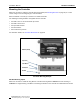
Controller Terminal Block
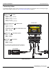
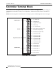
The controller provides a pluggable, 20-pin terminal block. In addition to the trigger input and power supply, the
terminal block accommodates a variety of I/O configurations. The illustration below shows the terminal block
pin-out.
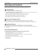
NOTE: Before working with the terminal block or connecting to power, read Warnings and Cautions on page 5.
------------------------------------------------------------------
Terminal Block Pin-Out Diagram
---------------------------------
1: 10 - 30V dc (V+)
2: dc Common (V-)
3: Trigger Device (input)
4: Strobe (out)
5: TX (transmit data)
6: RTS request to send (not used)
7: RX receive data (not used)
8: CTS clear to send (not used)
9: Programmable I/O 1
10: Programmable I/O 2
11: Programmable I/O 3
12: Programmable I/O 4
13: Programmable I/O 5
14: Programmable I/O 6
15: Product Change
16: Product Select 3
17: Product Select 2
18: Product Select 1
19: Product Select 0
20: Chassis Ground
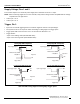
Supply Voltage
RS-232
Programmable I/O
Product Select