
Safety Controller with Ethernet Instruction Manual
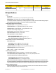
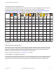

Signal Change-of-State Types
Two change-of-state (COS) types can be used when monitoring dual-channel safety input device signals: Simultaneous or Concurrent.
The rules for each circuit type are shown in the table below.
Input Circuit
Input Signal COS Timing Rules
Stop State—SO turns OFF when¹: Run State—SO turns ON when²:
Dual-Channel A and B Complementary At least 1 channel (A or B) input is in
the Stop state.
Simultaneous. A and B are both in the
Stop state and then both in the Run
state within 3 seconds before outputs
turn ON.
Concurrent. A and B concurrently in
the Stop state, then both in the Run
state with no simultaneity, to turn out-
puts ON.
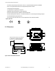
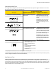
2 Terminals 3 Terminals 2 Terminals, PNP
24V
OFFON
Dual-Channel A and B
2-Ch, 2 Terminal
PNP
2-Ch, 2 Terminals 2-Ch, 3 Terminals 2-Ch, 4 Terminals
24V
ONON
2X Complementary A and B At least 1 channel (A or B) is within a
pair of contacts in the Stop state.
Simultaneous. A and B concurrently in
the Stop state, then contacts within a
channel in the Run state within 400 ms
(150 ms for 2-hand control), both chan-
nels in the Run state within 3 seconds
(0.5 seconds for 2-hand control)
Concurrent. A and B concurrently in
the Stop state, then contacts within a
channel in the Run state within 3 sec-
onds. Both channels in the Run state
with no simultaneity.
4 Terminals 5 Terminals
PNP
24V
OFFON OFFON
Dual-Channel Safety Mat
• Input channels are shorted togeth-
er (normal operation), or
• At least 1 of the wires is discon-
nected, or
• One of the normally low channels
is detected high, or
• One of the normally high channels
is detected low.
Each channel detects its own pulses.
2-Ch, 2 Terminals
¹ Safety Outputs turn OFF when one of the controlling inputs is in the Stop state.
² Safety Outputs turn ON only when all of the controlling inputs are in the Run state and after a manual reset is performed (if any safety
inputs are configured for Manual reset and were in their Stop state).
Signal Debounce Times
Closed-to-Open Debounce Time (from 6 to 100 milliseconds in 1 ms intervals, except 6 to 1,500 ms for mute sensors). The
closed-to-open debounce time is the time limit required for the input signal to transition from the high (24V dc) state to the steady low (0V
dc) state. This time limit may need to be increased in cases where high-magnitude device vibration, impact shock, or switch noise condi-
tions result in longer signal transition times. If the debounce time is set too short under these harsh conditions, the system may detect a
signal disparity fault and lock out. (Default setting is 6 ms.)
SC22-3/-3E Safety Controller Instruction Manual
30 www.bannerengineering.com - tel: 763-544-3164 P/N 133487 rev. C