
Safety Controller with Ethernet Instruction Manual


9 Troubleshooting
9.1 Cleaning
Disconnect power to the Controller and wring out excessive moisture from the cloth before cleaning.If cleaning of the polycarbon-
ate enclosure and display is required, wipe it down with a soft cloth that has been dampened with a mild detergent and warm water
solution.
9.2 Repairs and Warranty Service
The Controller is designed and tested to be highly resistant to a wide variety of electrical noise sources that are found in industrial set-
tings. However, intense electrical noise sources that produce EMI or RFI beyond these limits may cause a random trip or lockout condi-
tion. If random trips or lockouts occur, check that:
• The supply voltage is within 24V dc +/- 20%.
• The Safety Controller’s plug-on terminal blocks are fully inserted.
• Wire connections to each individual terminal are secure.
• No high-voltage or high-frequency noise sources or any high-voltage power lines are not routed near the Controller or alongside wires
that are connected to the Controller.
• Proper transient suppression is applied across the output loads.
The Safety Controller has no internal field-replaceable parts. If the Controller is not operating properly please contact the factory. In case
of a non-recoverable fault, do not open the housing of the Controller and do not attempt to repair the Controller yourself.
Contact a Banner factory applications engineer at a number listed in the beginning of this document. The applications engineer will at-
tempt to troubleshoot the Controller from your description of the problem. If he or she concludes that the Controller or a component is
defective, they will issue an RMA (Return Merchandise Authorization) number for your paperwork, and give you the proper shipping ad-
dress. Package the Controller carefully; damage which occurs during return shipping is not covered by warranty.
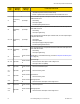
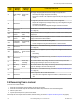
9.3 Troubleshooting—Finding and Fixing Faults
Depending on the configuration, the Safety Controller is able to detect a number of input, output and system faults, including:
• A stuck contact
• An open contact
• A short betweeen channels
• A short to ground
• A short to a voltage source
• A short to another input
• A loose or open connection
• An exceeded operational time limit
• A power drop
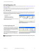
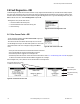
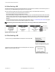
When a fault is detected, a message describing the fault is displayed in the fault diagnostics menu. An additional message may also be
displayed to help remedy the fault. The following troubleshooting table summarizes the faults and suggests additional checks to find the
cause of the problem. The following sections describe how to recover from a lockout and how to access fault information, using either the
PCI or the OBI.
If a problem with network communications occurs, a network user’s guide, available on www.bannerengineering.com, may be helpful.
SC22-3/-3E Safety Controller Instruction Manual
82 www.bannerengineering.com - tel: 763-544-3164 P/N 133487 rev. C